


46(86)
Control keypad
7
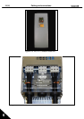
7. CONTROL KEYPAD
The control keypad is the link between the frequency converter and the user. The NX control
keypad features an alphanumeric display with seven indicators for the Run status (RUN,
,
READY, STOP, ALARM, FAULT)
and three indicators for the control place (I/O term/
Keypad/BusComm). There are also three Status Indicator LEDs (green - green - red), see Status
LEDs (green – green – red) below.
The control information, i.e. the number of menu, description of menu or the displayed value and
the numeric information are presented on three text lines.
The frequency converter is operable through the nine push-buttons of the control keypad.
Furthermore, the buttons serve the purposes of parameter setting and value monitoring.
The keypad is detachable and isolated from the input line potential.
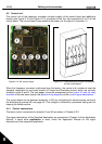
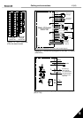
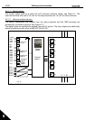
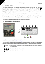
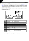
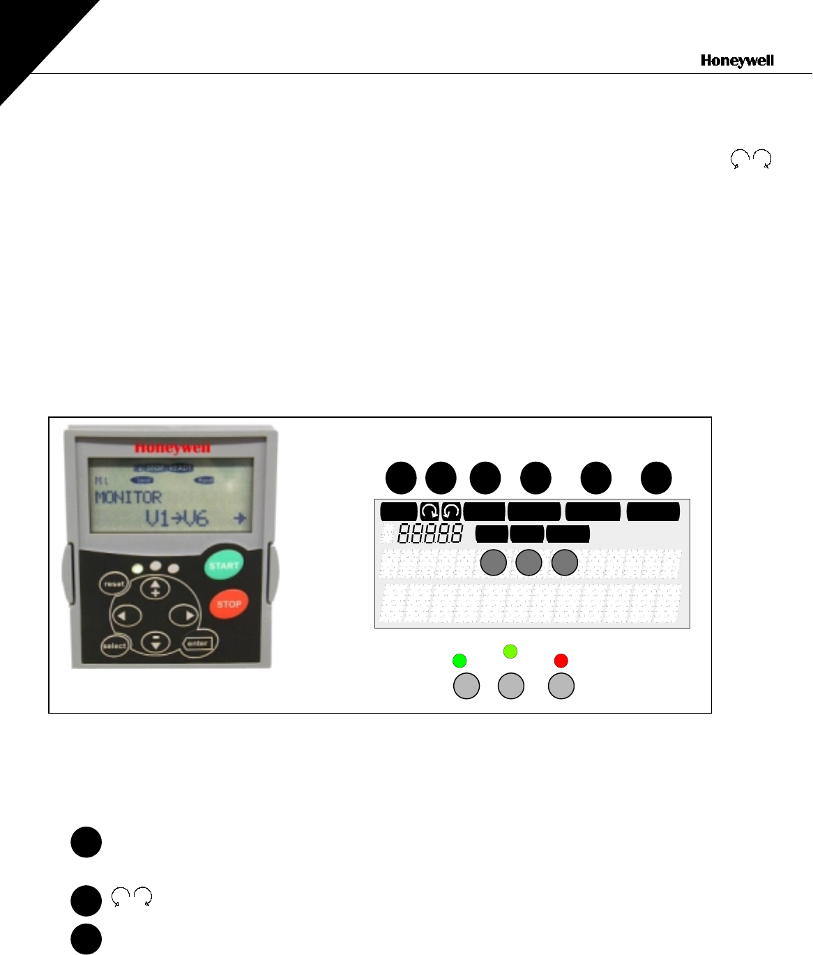
7.1 Indications on the Keypad display
Figure 7-1. The control keypad and drive status indications
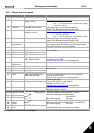
7.1.1
Drive status indications
(See control keypad)
The drive status indications tell the user what the status of the motor and the drive is, and whether
the motor control software has detected irregularities in motor or frequency converter functions.
RUN = Motor is running; Blinks when the stop command has been given but the frequency is
still ramping down.
= Indicates the direction of motor rotation.
STOP = Indicates that the drive is not running.
READY
FAULTSTOP
RUN
Bus/Comm
Keypad
I/O term
ALARM
run
ready fault
1 2 3 4 5 6
a b
I II III
•
••
•••
c
1
2
3