


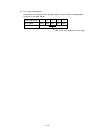
2 – 16
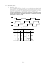
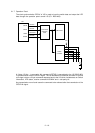
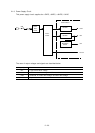
2.1.7 Operation Panel
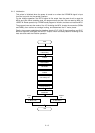
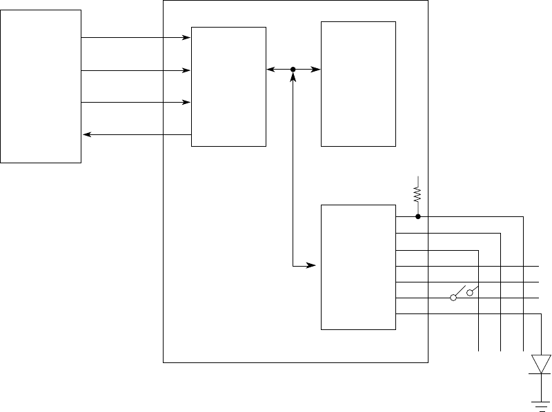
The clock synchronization OPCLK of LSI is used to input the switch data and output the LED
data through the operation panel control LSI (IC1: BU5148S).
LSI
OPTXD
OPCLK
OPCLR-N
OPRXD
77
78
80
OPTD
OPCK
NPA2
OPRD
Command
and Data
latch
LED Driver
Switch
controller
+5V
79
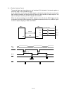
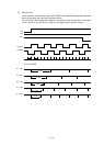
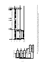
A 2-byte (15 bits + 1 even parity bit) command (OPTXD) is transmitted to the LSI (BU5148S)
in synchronization with the OPCLK signal. The LSI decodes this command and when it is found
to be legal, returns a 2-byte command response back to the LSI which includes data on Switch
information, LED status, receive command ACK/NAK and 1 odd parity bit.
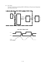
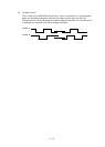
Any transmission errors found cause the command to be reissued after the transmission of the
OPCLR-N signal.