


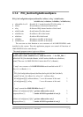
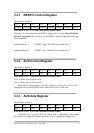

3.3.1 RESET\ Control Register
(Read/Write): wBase+0
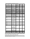
Bit 7 Bit 6 Bit 5 Bit 4 Bit 3 Bit 2 Bit 1 Bit 0
Reserved Reserved Reserved Reserved Reserved Reserved Reserved RESET\
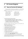
Note. Refer to Sec. 3.1 for more information about wBase.
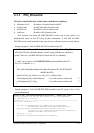
When the PC is first power-on, the RESET\ signal is in Low-state. This will disable
all D/I/O operations. The user has to set the RESET\ signal to High-state before any
D/I/O command.
outportb(wBase,1); /* RESET\=High Æ all D/I/O are enable now */
outportb(wBase,0); /* RESET\=Low Æ all D/I/O are disable now */
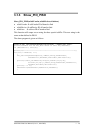
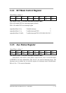
3.3.2 AUX Control Register
(Read/Write): wBase+2
Bit 7 Bit 6 Bit 5 Bit 4 Bit 3 Bit 2 Bit 1 Bit 0
Aux7 Aux6 Aux5 Aux4 Aux3 Aux2 Aux1 Aux0
Note. Refer to Sec. 3.1 for more information about wBase.
Aux?=0Æ this Aux is used as a D/I
Aux?=1Æ this Aux is used as a D/O
When the PC is first power-up, All Aux? signal are in Low-state. All Aux? are
designed as D/I for all PIO/PISO series. Please set all Aux? in D/I state.
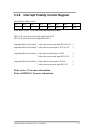
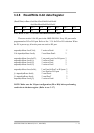
3.3.3 AUX data Register
(Read/Write): wBase+3
Bit 7 Bit 6 Bit 5 Bit 4 Bit 3 Bit 2 Bit 1 Bit 0
Aux7 Aux6 Aux5 Aux4 Aux3 Aux2 Aux1 Aux0
Note. Refer to Sec. 3.1 for more information about wBase.
When the Aux? is used as D/O, the output state is controlled by this register.
This register is designed for feature extension, so don’t control this register now.
OME-PIO-D96 User Manual (Ver.1.1, Mar/2003) ---- 31