


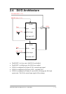

2.2 I/O port Location
There are twelve 8-bit I/O ports in the OME-PIO-D96. Every I/O port can be
programmed as D/I or D/O port. When the PC is first powered up, all twelve ports are
used as D/I port. The I/O port location is given as follows:
Connector of OME-PIO-D96 PA0 ~ PA7 PB0 ~ PB7 PC0 ~ PC7
CN1 Port0 Port1 Port2
CN2 Port3 Port4 Port5
CN3 Port6 Port7 Port8
CN4 Port9 Port10 Port11
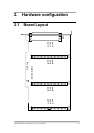
Refer to Sec. 2.1 for board layout & I/O port location.
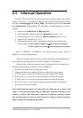
Note: Each PC0 can be used as interrupt signal source. Refer to Sec. 2.5 for more
information.
2.3 Enable I/O Operation
When the PC is powered up, all D/I/O ports are disabled. The enable/disable
of D/I/O is controlled by the RESET\ signal. Refer to Sec. 3.3.1 for more information
about RESET\ signal. The power-up states are given as follows:
• All D/I/O operations are disabled
• All twelve D/I/O ports are configured as D/I port
• All D/O latch register are undefined.(refer to Sec. 2.4)
The user has to perform some initialization before using these D/I/Os. These
recommended steps are given as follows:
Step 1: find address-mapping of PIO/PISO cards (refer to Sec. 3.1)
Step 2: enable all D/I/O operation (refer to Sec. 3.3.1)
Step 3: configure the first three ports to their expected D/I/O state & send the
initial value to all D/O ports (refer to Sec. 3.3.7)
Step 4: configure the other three ports to their expected D/I/O state & send
the initial value to all D/O ports(refer to Sec. 3.3.7)
Refer to DEMO1.C for demo program.
OME-PIO-D96 User Manual (Ver.1.1, Mar/2003) ---- 7