


4.10 D/A Circuit
The DAQP series PC card is equipped with two D/A channels. The 12-bit D/A converter is a
serial converter supporting synchronous update and is configured for a bipolar output range
from -5V to +5V. The 12-bit output data format is always in 2’s complement (right justified),
with the upper 4 bits indicating the output channel number (binary ‘0000’ for channel 0 and
‘0001’ for channel 1).
The D/A data port occupies two bytes (write only) in the I/O space, base + 8 being the low
byte and base + 9 the high byte. It is recommended that the data port be accessed with a single
16 bit I/O write instruction. If an 8 bit I/O instruction is used, the low byte should be written
first, followed by the high byte.
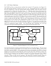
The serial link from the D/A port to the D/A converter contains a 16 bit buffer register and a
16 bit shift register. A data word written into the D/A port is first written into the buffer
register, then is loaded to the shift register and finally sent to the input register of the
corresponding D/A channel. Bit 5 of the auxiliary status register (base + 15, read) indicates
whether the D/A port buffer register is occupied (‘1’) or empty (‘0’). It is recommended that
the D/A port be accessed only when this bit is “0” to prevent possible data loss or corruption.
Inside the D/A converter, each channel has a 16 bit shift register, plus a 12 bit input and a 12
bit output register. The data loaded to the output register determines the analog output of the
D/A channel.
The DAQP series PC card has 4 D/A operation modes (mode 0 to 3). Mode 0 is the direct
update mode. The corresponding D/A channel output register will be updated immediately
after the data word is written into the D/A port (if byte I/O is used, after the high byte is
written). There is no synchronization between the two channels in this mode.
Modes 1, 2 and 3 all use synchronized update in which the two D/A channels are updated
synchronously upon certain event. In mode 1, the event is the independent timer/counter
overflow. In mode 2, the event is external gate control moving from low to high. In mode 3,
the event is the pacer clock. In synchronous update modes, the data word written to each D/A
channel will be buffered in it’s input register first and then gets loaded into the output register
when the corresponding event (depending on the mode) is received. Synchronous update
modes can be used to generate waveforms with accurate phase requirements, such as
orthogonal sinusoidal waveforms (sine and cosine).
4.11Timer/Counter
In addition to the 24 bit pacer clock, the DAQP series card is equipped with an independent
16 bit timer/counter. It has an internal clock source of 1 MHz and an external clock input that
is shared with the pacer clock external input. The timer circuit contains a 16 bit reload register,
a 16 bit up-counter and a 16 bit read-latch register. The reload register holds the initial value
for the counter. The initial value is also set each time it overflows. The read-latch register will
latch the current count of the counter each time it receives the latch command (writing ‘1’ into
DAQP-208/208H/308 Users Manual 35