


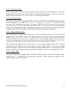
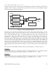
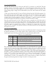
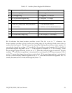


Table 5-22. Auxiliary Status Register Bit Definition
1 = FIFO empty, 0 = Not empty
A/D data FIFO empty flag
0
1 = FIFO almost full, 0 = Not yet
A/D data FIFO almost full flag
1
1 = Data lost latched, 0 = Not yetData lost event latch2
1 = Either EOS or FIFO almost full
event has been latched
0 = Neither event has been latched yet
A/D conversion event latched (Logic
“OR” of A/D EOS and FIFO almost full
event latches)
3
1 = Overflow latched, 0 = Not yet
Timer/Counter overflow event latch
4
1 = Occupied, 0 = EmptyD/A port buffer register flag5
1 = Triggered, 0 = Not yet
A/D trigger flag
6
1 = Running, 0 = Idle
A/D running flag
7
ExplanationFunctionBit
Bit 4 indicates the timer/counter overflow event. This bit is set to ”1” whenever the
timer/counter overflow occurs (on the next rising edge of the selected clock source after it
reaches the final count). This bit cannot be cleared by reading the auxiliary status register. It
can only be cleared by writing a “0” into bit 5 of the auxiliary control register. Bit 5 is the D/A
port buffer register flag and is set to “1” if the register is occupied or “0” if it is empty. With
the pre-trigger option selected, bit 6 is set to “1” when the external trigger is received. This bit
remains “1” until data acquisition is terminated by receiving the A/D stop command. Bit 6
set to “0” means the trigger has not been received yet. If the pre-trigger option is not selected
or bit 6 of the auxiliary control register is set to “0”, then this bit should be ignored. Bit 7 is
exactly the same as bit 6 in the status register (base + 2).
DAQP-208/208H/308 Users Manual 58