


5
.
2
Address Map
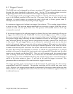
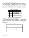
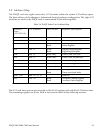
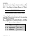
The DAQP card uses eight consecutive I/O locations within the system I/O address space.
The base address of the adapter is determined during hardware configuration. The eight I/O
locations are used by the DAQP card as summarized in the following table.
Table 5-4. DAQP Series Card Address Map
Auxiliary Control Register
Auxiliary Status Register
Write
Read
base + 15
1111
reserved
base + 12, 13, 14
1100 - 1110
Timer port
(re-load)
Timer port (read latch)
Write
Read
base + 10, 11
1010 - 1011
D/A port
Write Only
base + 8, 9
1000 - 1001
Command Register
Write Only
base + 7
0111
Pacer Clock, high byte
Write Only
base + 6
0110
Pacer Clock, middle byte
Write Only
base + 5
0101
Pacer Clock, low byte
Write Only
base + 4
0100
Digital Output Register
Digital Input Register
Write
Read
base + 3
0011
Control Register
Status Register
Write
Read
base + 20010
Scan List (Queue)Write Onlybase + 10001
Data FIFORead/Writebase + 00000
Register Description
Port Access
I/O Address
Address
Lines
(A3A2A1A0)
The D/A and timer port can be accessed as 16 bit I/O registers and with 8 bit I/O instructions.
The remaining registers are 8 bits. Each is discussed in detail in the following sections.
DAQP-208/208H/308 Users Manual 39