


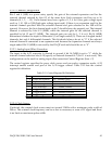
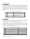
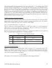

5.2.3 Status Register (base + 2)
The status register is read only and shares the same offset as the control register. It reports
data FIFO flag, A/D interrupt and A/D conversion status. Table 5-13 lists the status register
bit definition.
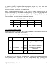
Table 5-13. Status Register Bit Definition
0/1 : false / true
Data FIFO empty
0
0/1 : false / trueData FIFO almost full1
0/1 : false / trueData FIFO full2
0/1 : no / yesFIFO threshold event3
0/1 : no / yes
End of scan event
4
0/1 : no / yes
Data lost event
5
0/1 : no / yesA/D running status6
0/1 : busy / idleScanning status7
Explanation
Status
Bit
Bit 7 shows the scan status and is set to “0” when the DAQP card is scanning the input
channels specified by the scan list and then “1” upon scan completion.
Bit 6 is the A/D running flag. A “1” here indicates indicates the DAQP card has been
triggered and is acquiring data (busy), while a “0” means it is idle. If the pre-trigger is
selected, this bit will be set as soon as the arm command is received. If pre-trigger is not
selected, then this bit will be set after a trigger is received.
Bit 3, 4 and 5 are the event latches. When an event is detected, the corresponding bit will be set
to “1” until the status register is read which then clears all event bits to “0”. Bit 5 is used for
data lost events, bit 4 for end-of-scan (EOS) events and bit 3 for the FIFO threshold event.
When the corresponding interrupt is enabled, a “1” in bit 3 (or bit 4) will also cause an
interrupt. Bits 0, 1 and 2 are the data FIFO flags.
Each time the status register is read, the latched events (bits 3, 4 and 5) will be cleared. This
structure is very efficient, yet it can cause events to be lost if the read action overwrites the
event setting so that the corresponding event gets lost. This can be critical in a tight
“check-and-wait” loop where the status register is read and checked for the expected events to
occur.
DAQP-208/208H/308 Users Manual 48