


5
.
2
.
2
.
2
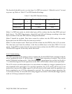
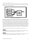
Channel Configuration
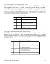
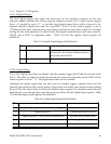
Bits 5 and 4 (LSB) in a queue entry specify the gain of the external expansion card for the
external channel selected by bits 0-3 of the same byte. Each expansion card has up to 16
channels (0, 1, 2, ..., 15). Each channel may have a gain of 1, 2, 4 or 8 (low gain voltage input
card) or 1, 10, 100 or 1000 (high gain voltage input card). If there is no expansion card for the
internal channel specified then the external channel and gain selection in the LSB will be
ignored. However, the first channel mark on bit 7 should always be properly set. The internal
channel is selected by bits 8-11 (MSB), while the internal gain for the selected channel is
specified by bit 12 and 13 (MSB). The internal gain can only be 1, 2, 4 or 8. Bit 14 (MSB)
determines whether the input is differential (1) or single-ended (0). There are 8 singled-ended
channels, but only 4 differential channels. This bit should always be set to “0” if the selected
internal channel is connected to an expansion card because the expansion channels are always
single-ended. Bit 15 (MSB) is not used by the DAQP card and should be set to “0”.
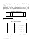
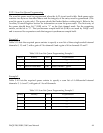
5.2.2.3 Analog Input Offset Correction
The input to the A/D converter is shorted to ground if bit 14 (MSB) is set to “1” while the
internal channel selection bits (8-10) specify an internal channels 4-7 (bit 11 is not used). This
configuration can be used for analog input offset correction.Control Register (base + 2)
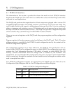
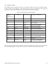
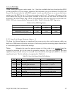
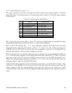
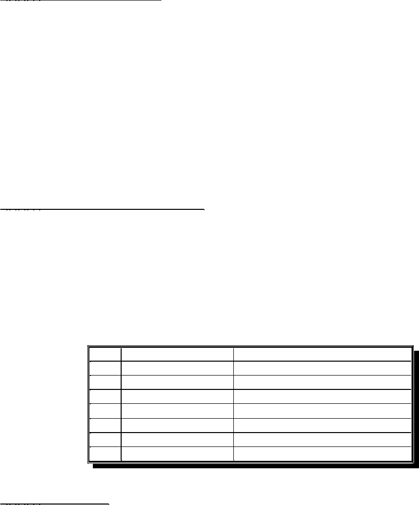
The control register specifies the pacer clock source and pre-scaler, expansion mode, A/D
interrupt enable control and part of the A/D trigger control. Table 5-12 lists the control
register bit definition.
Table 5-12. Control Register Bit Definition
0/1 : rising/falling
Trigger edge
0
0/1 : internal/externalTrigger source1
0/1 : one-shot/continuousTrigger mode2
0/1 : disable/enable
FIFO interrupt
3
0/1 : disable/enable
EOS interrupt
4
0/1 : disable/enable
Expansion mode
5
00 : External clock
01 : Internal, 5 MHz
Pacer clock source
and pre-scaler
7-6
Explanation
Function
Bit
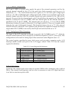
5.2.2.4 Clock Source
If selected, the external clock source must not exceed 5 MHz with a minimum pulse width of
200 ns. The external clock frequency can be as low as necessary or even a DC signal and there
is no limit on maximum pulse width.
DAQP-208/208H/308 Users Manual 45