82
Procedure Before Using FINS Communications Section 5-2
5-2 Procedure Before Using FINS Communications
Note The location of the local IP address setting depends on the type of CPU Unit
in the following way.
CS Series: Rotary switches on back of Ethernet Unit.
CJ Series: CPU Bus Unit System Setup or allocated words in the DM Area.
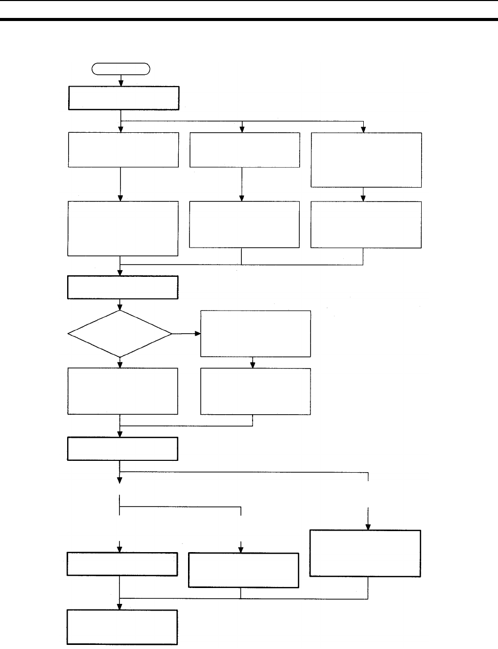
Start
Determine the address conversion
method for the destination IP address.
Automatic Generation
Automatically converted from
FINS node number.
IP Address Table
Converted from table of corre-
spondences between FINS node
numbers and IP addresses.
Combined Method
IP address table is referenced;
if IP address is not registered,
then it is converted from FINS
node number.
Set the IP address (see note) so
that the host number's least
significant byte = the FINS node
number.
Select the IP table address
method for the address conver-
sion method in the System Set-
up, and create an IP address
table.
Select the combined method for
the address conversion method
in the System Setup, and create
an IP address table.
Determine the FINS UDP port number.
Is the FINS UDP port number
other than 9600?
Ye s
No
In the System Setup, select
"user-defined" as the method
for specifying the FINS UDP
port number.
Set the FINS UDP port number
for all Ethernet Units on the
Ethernet network to the default
of 9600.
Set the FINS UDP port numbers
for all of the Ethernet Units on
the Ethernet network to the
same value.
Determine the network configuration.
Communications with PC on local network
Communications with PC on another
network (such as Controller Link)
The only Communications Units
mounted are Ethernet Units.
Communications Units other than
Ethernet Units are also mounted.
Routing table settings are not
required.
Use the CX-Programmer to set
the local network table at the
CPU Unit.
Use the CX-Programmer to set
the local network table and the
relay network table at the CPU
Unit.
Create a user program for issuing
FINS messages by SEND(090),
RECV(098), and CMND(490).


