Packard Bell iPower GX Disassembly Manual
6
2. Use the thumb notch to lift the bay cover and remove it. Be careful not to break off the tabs
located on the end of the cover opposite the thumb notch (see Fig. 4).
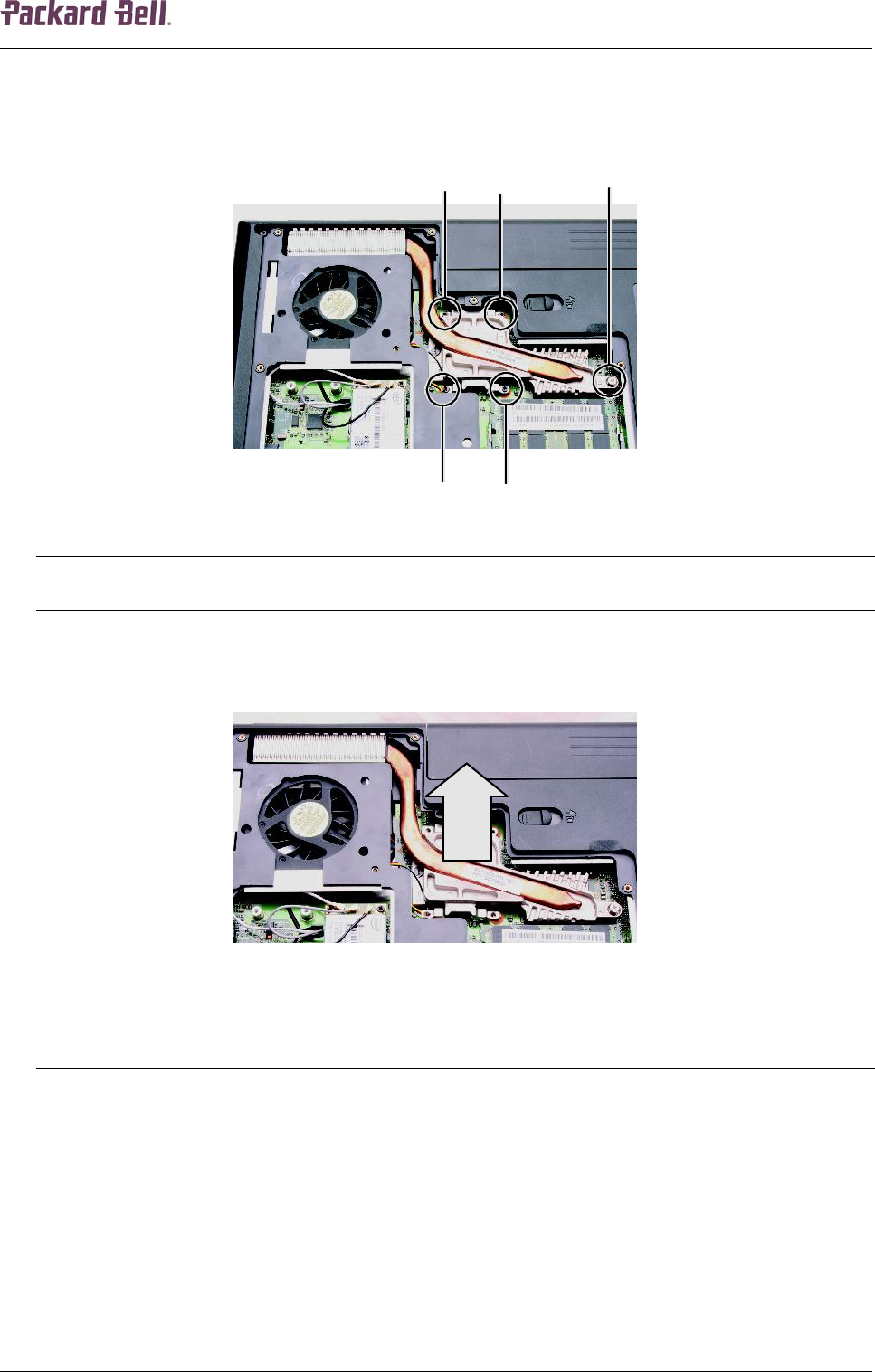
3. Loosen the screws that secure the heat sink to the system board. Use the numbers
stamped in the metal next to each screw and loosen the screws in reverse numerical order
(start with 5, then 4, then 3, then 2, and finally 1).
Fig. 7 Location of the CPU heat sink screws.
Note:
Screws 1 to 4 are captive and you cannot remove them. When tightening the heat sink screws into the
numbered holes during re-assembly, tighten them in numerical order.
4. At the same time as you lift, move the heat sink away from the side of the notebook, and
remove the heat sink.
Fig. 8 Removing the CPU heat sink.
Note:
Before re-assembling the heat sink, remove any thermal grease residue from the CPU using a soft cloth and
isopropyl alcohol. Apply new thermal grease on the CPU; use only enough to cover the CPU die.
CPU
To remove the CPU, first remove the heat sink (see CPU Heat Sink on page 5) and then perform
the following steps:


