


-6-
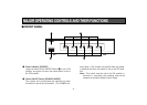
CAMERA
CONTROL OUT
CAMERA
CONTROL IN
VIDEO OUT
PAM/TILT
CONTROL OUT
PAM/TILT
CONTROL IN
S-VIDEO OUT
VIDEO
IN
G/L
OUT
G/L
IN
CAMERA
CONTROL OUT
VIDEO OUT
PAM/TILT
CONTROL OUT
S-VIDEO OUT
VIDEO
IN
G/L
OUT
CAMERA
CONTROL OUT
VIDEO OUT
PAM/TILT
CONTROL OUT
S-VIDEO OUT
VIDEO
IN
G/L
OUT
CAMERA
CONTROL OUT
VIDEO OUT
PAM/TILT
CONTROL OUT
S-VIDEO OUT
VIDEO
IN
G/L
OUT
CAMERA
CONTROL OUT
VIDEO OUT
PAM/TILT
CONTROL OUT
S-VIDEO OUT
VIDEO
IN
G/L
OUT
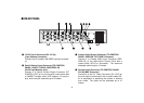
4 3 2 15
DC12V IN
TO CAMERA PAM/TILT HEAD TO CONTROL PANEL
PREVIEW OUT
SEE MANUAL
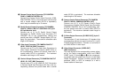
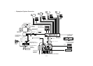
t 12V DC Input Connector [DC 12V IN]
(4-pin Cannon Connector)
Connect the AC Adaptor AW-PS505 (optional accesso-
ry).
y Pan/tilt Control Input Connector [TO CONTROL
PANEL, PAN/TILT HEAD, CONTOROL IN]
(RJ-45 8-pin Modular Jack)
Connect it to Pan/tilt Control Output Connector [P/T
CONTROL OUT] on the multi hybrid control panel with
a 10BASE-T straight cable (UTP category 5 or equiva-
lent), which may be extended up to 10 meters.
u Preview Video Output Connector [TO CONTROL
PANEL, PREVIEW OUT] (BNC Connector)
Connect it to Preview Video Input Connector [PRE-
VIEW IN] on the Multi-Hybrid Control Panel with a
coaxial cable (5C-2V or equivalent). The maximum
allowable cable length is 10 meters.
i Genlock Input Connector [TO CONTROL PANEL,
G/L IN] (BNC Connector)
Connect it to the G/L Onput Connector [G/L OUT] on
the multi hybrid control panel with a coaxial cable (5C-
2V or equivalent) in operating the camera in external
sync mode. The cable can be extended up to 10
meters.
■ REAR PANEL