


- 25 -
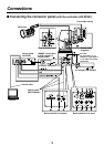
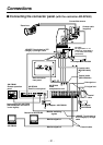
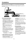
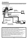
9Pb OUT connector
This is for camera video signal output.
Connect this to the Pb IN connector on
the controller or to a monitor, etc.
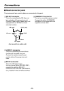
Use a coaxial cable (BELDEN 8281) for
the connecting cable.
:G/L IN connector
This is for genlock signal input.
Connect this to the G/L OUT connector
on the controller.
Use a coaxial cable (BELDEN 8281) for
the connecting cable.
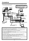
;VIDEO OUT connector
This is for camera video signal output.
Connect this to the VIDEO IN connector
on the controller or to a monitor, etc.
Use a coaxial cable (BELDEN 8281) for
the connecting cable.
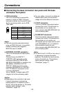
<CAMERA CONTROL IN connector
This is for camera control signal input.
Connect this to the CAMERA
CONTROL OUT connector on the
controllers AW-RP501/AW-RP505, or
multiport hub AW-HB505.
Use a coaxial cable (BELDEN 8281) for
the connecting cable.
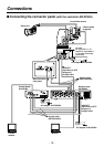
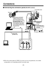
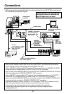
=CONTROL IN RS-232C connector
This is for RS-232C control signal input
from the personal computer.
Use the AW-CA28T9 cable (option) for
the connecting cable.
The AW-CA28T9 is 10m long. When
extending the length, please use an
RS-422, converting back to the
RS-232C at the pan/tilt head.
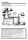
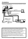
<Notes>
OThe personal computer can be
connected with the controllers
AW-RP301/AW-RP305/AW-RP501/
AW-RP505 at the same time. (When
connecting with the controllers
AW-RP605A/AW-RP400 at the same
time, connect with controller’s REMOTE
terminal.) In that case, the control source
last used for operation is given priority.
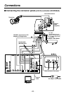
OWhen the AW-RP301, AW-RP305,
AW-RP501 or AW-RP505 controller and
a personal computer are to be used at
the same time, the camera is controlled
by the controller if the controller is
connected to the < CAMERA
CONTROL IN connector. If this
connector is not connected, it is
controlled by the personal computer.
OInformation such as pan/tilt head
position, lens zoom, focus, iris, etc. can
be accessed by the computer however,
white balance set by the controller
cannot be accessed.
Connections