


- 31 -
Connections
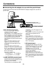
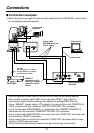
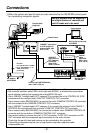
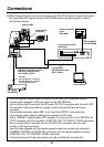
5When the camera and pan/tilt head are to be controlled by the AW-RP505 control panel
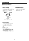
for transmitting component signals
• Use the supplied camera cable to connect the unit with the convertible camera.
• Set controller selection switch SW1 to the right side (RP501), and select the transmission
signal selection setting that supports the analog/IEEE1394 card.
• Use a 10BASE-T straight cable (UTP category 5) to connect the unit’s CONTROL IN IP/RP
connector with the multiport hub’s PAN/TILT CONTROL OUT connector.
• Use a coaxial cable (BELDEN 8281) to connect the unit’s CAMERA CONTROL IN connector
with the multiport hub’s CAMERA CONTROL OUT connector.
• Use a 10BASE-T straight cable (UTP category 5) to connect the multiport hub’s PAN/TILT
CONTROL IN connector with the controller’s PAN/TILT CONTROL OUT connector.
• Use a coaxial cable (BELDEN 8281) to connect the multiport hub’s CAMERA CONTROL IN
connector with the controller’s CAMERA CONTROL OUT connector.
• Use coaxial cables to connect the unit’s Y OUT connector, Pr/SDI OUT connector and Pb
OUT connector with the component input connectors on the color monitor.
• Check that the pan/tilt head and camera can be controlled by the controller.
• Transmitting component signals over a long distance requires a separate cable
compensation unit.
Multiport hub:
AW-HB505
AC adapter:
AW-PS300A
Color monitor
Camera cable
(supplied)
10BASE-T (equivalent
to UTP category 5)
straight cable, max.
33 ft. (10 m)
10BASE-T
(equivalent to
UTP category
5) straight
cable, max.
1640 ft. (500 m)
Coaxial cable (BELDEN 8281),
max. 1640 ft. (500 m
)
Coaxial
cable
(BELDEN
8281), max.
33 ft. (10 m
)
Coaxial cable
Genlock signals must be supplied if
a multiple number of cameras and
pan/tilt heads are to be used.
Multi hybrid control panel:
AW-RP505
DC cable
(UL Type SPT-2 2!16 AWG
or UL Type NISPT-2 2!16
AWG, to be locally
purchased)