


- 39 -
Connections
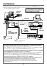
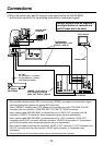
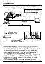
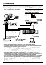
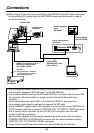
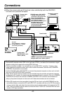
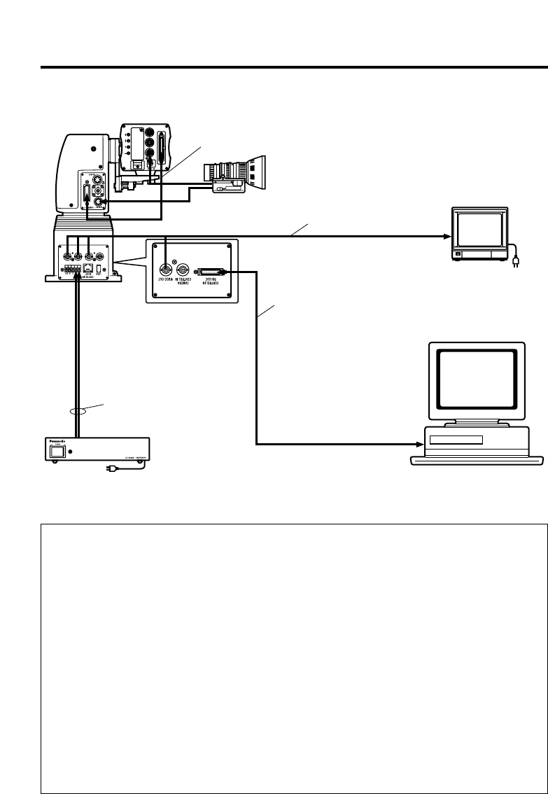
=When the camera and pan/tilt head are to be controlled by a personal computer or other
such unit
• Use the supplied camera cable to connect the unit with the convertible camera.
• Set controller selection switch SW1 to the right side (RP501), and select the
transmission signal selection setting that supports the analog/IEEE1394 card.
• Use the RS-232C cable (AW-CA28T9) to connect the personal computer or other such
unit with the unit’s CONTROL IN RS-232C connector.
• Use coaxial cables to connect the unit’s VIDEO OUT connector or Y OUT connector,
Pr/SDI OUT connector and Pb OUT connector with the color monitor’s VIDEO input
connector or component input connectors.
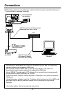
• Check that the pan/tilt head and camera can be controlled by the controller.
• Transmitting video signals over a long distance requires a separate cable
compensation unit.
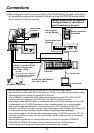
❈ When SDI signals are to be transmitted, plug the SDI card (such as the AW-PB504N)
into the convertible camera, connect the SDI card’s SDI OUT connector with the unit’s
SDI IN connector using a coaxial cable, and select the transmission signal selection
setting that supports the SDI card. Then use another coaxial cable to connect the
unit’s Pr/SDI OUT connector with the color monitor’s SDI input connector.
Personal computer
(Windows)
AC adapter:
AW-PS300A
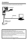
Color monitor
Camera cable
(supplied)
RS-232C cable: AW-CA28T9
• The BNC connectors are not
connected to the pan/tilt head.
• When using RS-232C for
control, the maximum length
of the RS-232C cable is
50 ft. (15 m). To further extend
the cable length, convert
RS-232C to RS-422 and
convert it back to RS-232C at
the pan/tilt head side.
Coaxial cable
DC cable
(UL Type SPT-2 2!16 AWG or
UL Type NISPT-2 2!16 AWG,
to be locally purchased)