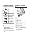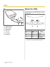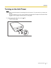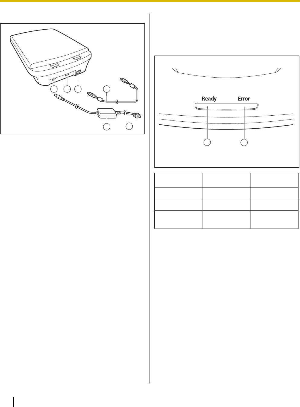
Rear
1 2 3
6
5
4
A Power connecter
B USB connecter
C Power switch
D USB cable
E AC adaptor
F Power cord
About the LEDs
The status of the unit is indicated by the combination of
the LED (Green) (A) and LED (Red) (B), as shown in
the table below:
1
2
A LED (Green) B LED (Red) Status
ON OFF Ready
ON ON Error
*1
Blink OFF
Scanning/
Warming up
*1
Check the status of the unit using User Utility. For details about
User Utility, refer to the User Utility Reference Manual.
12 Operating Instructions
Installation


