


Chapter 2 Getting Started — Connecting
32 - ENGLISH
Attention
f Always use one of the following when connecting a VCR.
g A VCR with built-in time base corrector (TBC)
g A time base corrector (TBC) between the projector and the VCR
f If nonstandard burst signals are connected, the image may be distorted. In such case, connect the time base corrector (TBC) between the
projector and the external devices.
f Use a commercial HDMI/DVI conversion cable with a ferrite core.
f Ask a qualied technician or your dealer to install the cable wiring for a twisted-pair-cable transmitter and the projector. Image and sound
may be disrupted if cable transmission characteristics cannot be obtained due to inadequate installation.
f For the LAN cable between a twisted-pair-cable transmitter and the projector, use a cable that meets the following criteria:
g Compatible with CAT5e or higher
g Shielded type (including connectors)
g Straight-through
g Single wire
f When laying cables between a twisted-pair-cable transmitter and the projector, check that cable characteristics are compatible with CAT5e
or higher using tools such as a cable tester or cable analyzer.
When using a relay connector midway, include it in the measurement.
f Do not use a hub between a twisted-pair-cable transmitter and the projector.
f When connecting to the projector using a twisted-pair-cable transmitter (receiver) of other manufacturer, do not place another twisted-pair-
cable transmitter (receiver) between the twisted-pair-cable transmitter of other manufacturer and the projector. This may cause sound and
image to be disrupted.
f Do not pull cables forcefully. Also, do not bend or fold cables unnecessarily.
f To reduce the effects of noise as much as possible, stretch out the cables between the twisted-pair-cable transmitter and the projector
without any loops.
f Lay the cables between a twisted-pair-cable transmitter and the projector away from other cables, particularly power cables.
f When installing multiple cables, run them side by side along the shortest distance possible without bundling them together.
f After laying the cables, conrm that the value of [SIGNAL QUALITY] in the [NETWORK] menu → [DIGITAL LINK STATUS] is displayed in
green (indicates normal quality). (x page 99)
Note
f For an HDMI cable, use an HDMI High Speed cable that conforms to HDMI standards. If a cable that does not conform to HDMI standards
is used, images may be interrupted or may not be displayed.
f The projector does not support VIERA Link (HDMI).
f The maximum transmission distance between the twisted-pair-cable transmitter and the projector is 100 m (328'1"). If this distance is
exceeded, image and sound may be disrupted and may cause a malfunction in LAN communication. Please note that we do not support
the use of the projector outside the maximum transmission distance.
f For twisted-pair-cable transmitter of other manufacturers of which the operation has been veried with the DIGITAL LINK compatible
projector, refer to Panasonic website (http://panasonic.net/avc/projector/). Note that the verication for devices of other manufacturers
has been made for the items set by Panasonic Corporation, and not all the operations have been veried. For operation or performance
problems caused by the devices of other manufacturers, contact the respective manufacturers.
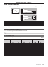
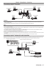
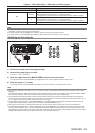
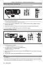
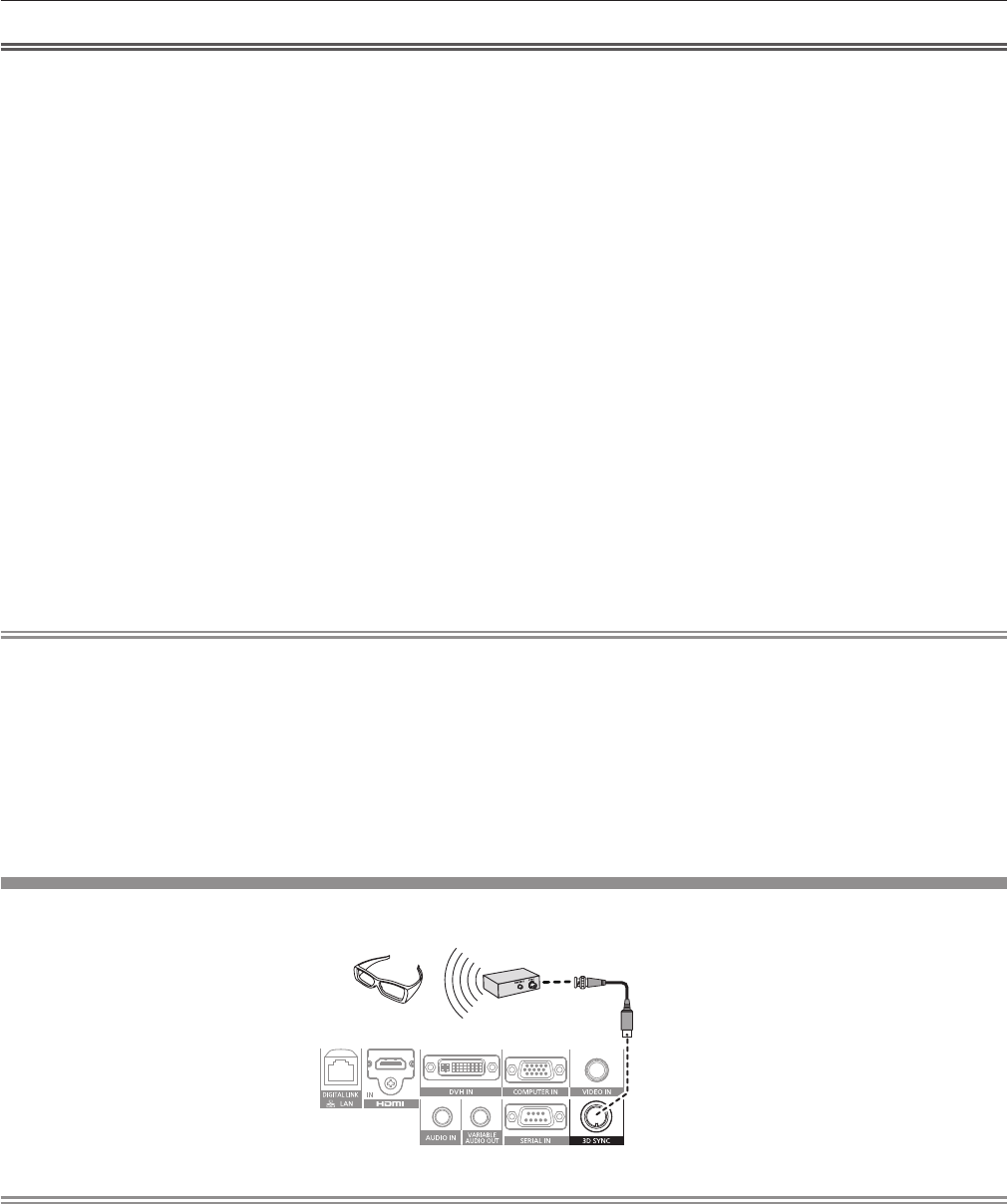
Connecting example: IR transmitter
VESA standard 3D eyewear
VESA standard IR transmitter
Note
f When viewing 3D images using VESA standard 3D eyewear, connect the commercially available VESA standard IR transmitter and set the
[3D SETTINGS] menu → [3D MODE] to [3D SYNC] or [DLP Link + 3D SYNC].
f When using 3D eyewear that supports DLP Link, an IR transmitter is not required.
When using 3D eyewear that supports DLP Link, set the [3D SETTINGS] menu → [3D MODE] to [DLP Link] or [DLP Link + 3D SYNC].