


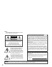
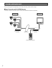
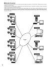

11
MAJOR OPERATING CONTROLS AND THEIR FUNCTIONS
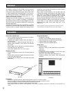
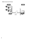
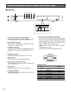
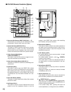
■ Front View
LINK/
10BASE-T
100
BASE-TX CONNECT ACT
LOW HIGH
RING.VOL
Network Interface Unit WJ-NT
POWER
ON
OFF
RS-232CRESET
HOST PORT
MODE
q w e r t y u
i o !0
q Power Switch & Power Indicator [POWER]
Press this switch to turn on or off the power of the unit.
The indicator lights while the power is turned on.
w [LINK/10BASE-T] indicator
Lights when communication is established through
lines (LINK) or a 10BASE-T LAN.
e [100BASE-TX] indicator
Lights when communication is established through a
100BASE-T LAN, along with the LINK/10BASE-T indica-
tor.
r [CONNECT] indicator
Lights when signaling the data only in H.261 mode.
t [ACT] indicator
Blinks when receiving and sending IP packets.
y Ringer Volume Control [RING. VOL]
Turn this control to adjust the sound level that beeps
when receiving a call.
u Ringer Buzzer
Beeps when receiving a call only in H.261 mode.
i Reset Button [RESET]
Pressing this button shuts down the current operation
and restarts the system.
o RS-232C Host Port [RS-232C HOST PORT]
The unit communicates with the host computer through
this D-Sub 9-pin connector. Setting the MODE DIP
switch #9 specifies the mode and usable port from
among RS-485 (Rear Panel) and RS-232C (Front
Panel). Available controls are as follows.
• Communication control such as calling and discon-
nection
• Up/Download for software
• Download for communication log and alarm log
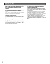
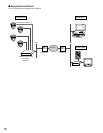
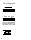
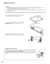
RS-232C
HOST PORT
q
yuio
wert
RS-232C Host Port
No.
Signal Function Direction as seen from
name WJ-NT204
1C D
Receiver carrier Input
detection
2 R D Receiving data Input
3 S D Sensing data Output
4 E R Data connection ready Output
5 S G Signal Ground –
6 D R Data set ready Input
7 R S Request send Output
8 C S Send enabled Input
9 N. C. (Not used)