


Installation
2-5
3166-A2-GB20-10
November 1998
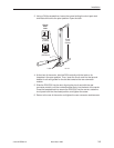
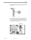
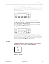
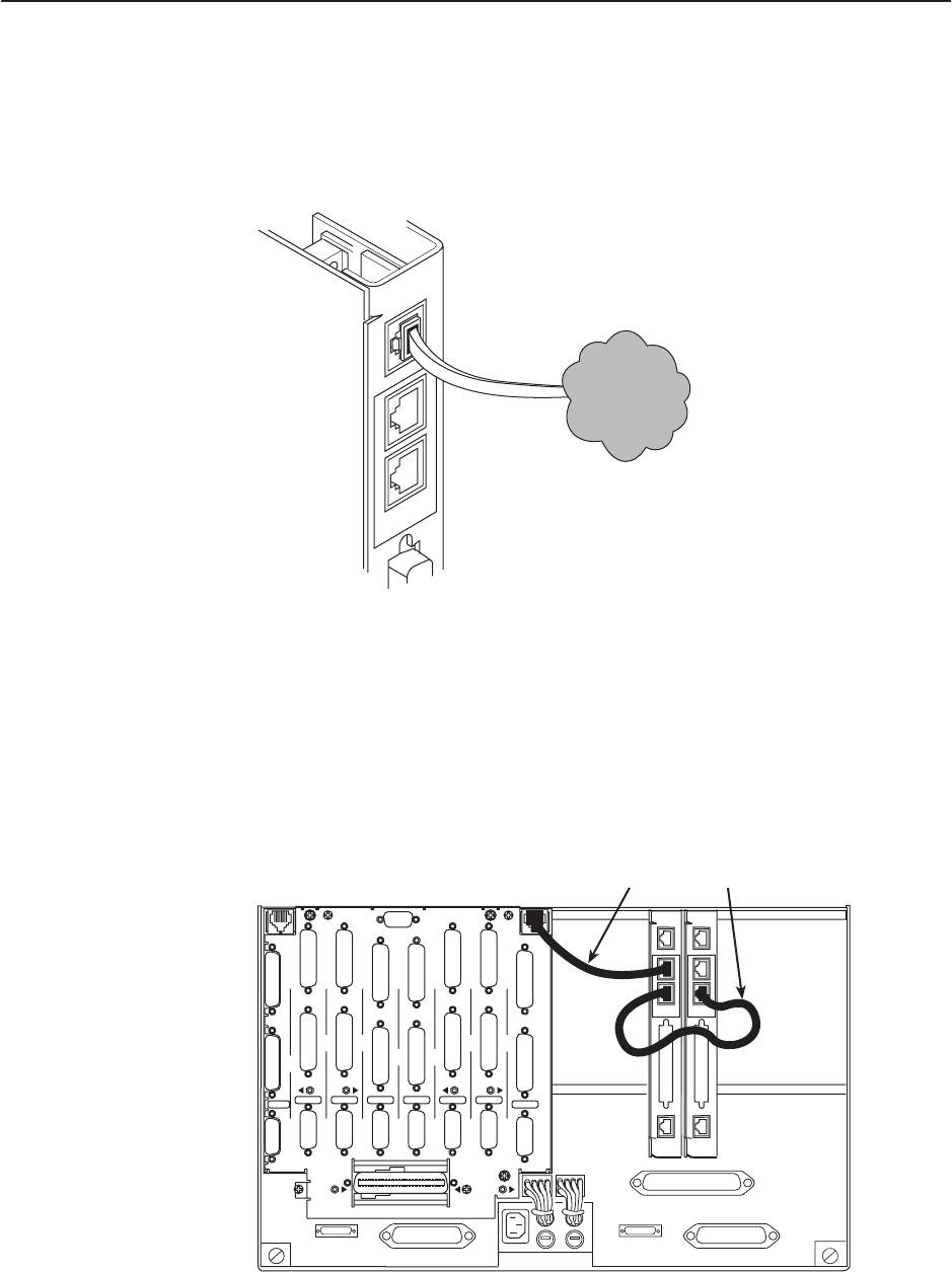
9. Attach the network cable to the NET connector on the rear connector module.
Connect the other end of the network cable to the connection provided by the
telephone company.
NET
DIAGNOSTIC
CHANNEL
Network
98-16077
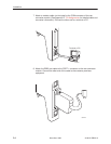
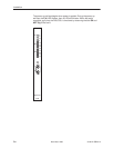
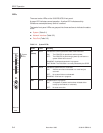
10. To daisy-chain the diagnostic channel with that of other 3166 DSU/CSUs or a
T1 auxiliary backplane, insert one end of the short diagnostic channel
extension cable into either DIAGNOSTIC CHANNEL connector on the rear
connector module. Insert the other end into either DIAGNOSTIC CHANNEL
connector of a neighboring 3166 rear connector module, or the diagnostic
channel connector of a T1 auxiliary backplane.
98-16080
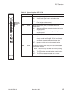
PORT
1
PORT
1
PORT
1
PORT
1
PORT
1
PORT
1
PORT
1
PORT
1
CLOCK IN
DIAGNOSTIC
CHAN
PORT
2
PORT
2
PORT
2
PORT
2
PORT
2
PORT
2
PORT
2
PORT
2
DTE
DTE DTE DTE DTE DTE DTE
DTE
SLT 8 (16)
SLOT 6 (14)
SLOT 7 (15)
SLOT 5 (13)
SLOT 4 (12) SLOT 3 (11)
SLOT 2 (10)
SLOT 1 (9)
T1 NETWORK
INTERFACE
COMCODE
107170409
MODEL NO.
3100-F1-900
DIAGNOSTIC
CHAN
CAUTION:
DISCONNECT ALL TELEPHONE LINES AT THE NETWORK
INTERFACE BEFORE TOUCHING OR SERVICING
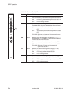
Diagnostic Channel
Extension Cable
NET
PORT 1
COM
DIAGNOSTIC
CHANNEL
NET
PORT 1
COM
DIAGNOSTIC
CHANNEL