COMSPHERE 3900 Series Modems
14-14 September 1998 3910-A2-GN32-40
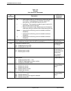
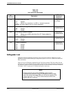
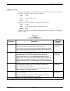
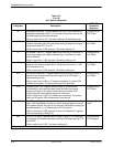
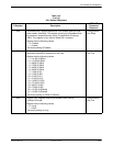
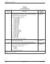
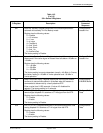
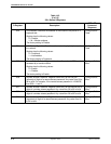
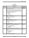
Table 14-2
(10 of 10)
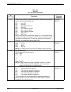
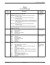
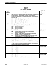
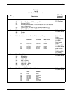
391x Series AT Commands
AT
Command
DCP LCD
Command
Sequence
Description
\Tn No Data Disconnect Timer.
\T0 Disable.
\Tn Where n is a value from 1 to 255 in 1-minute increments.
Configure\Edit\
Line Dialer
NOTE: The factory default value is country dependent.
\Xn XON/XOFF Passthrough Flow Control.
\X0 Disable.
\X1 Enable.
Configure\Edit\
V42/MNP/Buffer
%An Error Control Fallback Character.
%An Where n is an ASCII value from 0 to 127. Factory default is
013 ASCII.
Configure\Edit\
V42/MNP/Buffer
%Cn MNP5 Data Compression.
%C0 Disable.
%C1 Enable.
Configure\Edit\
V42/MNP/Buffer
″Hn
V.42bis Compression.
″H0 Disable.
″H1 Enable.
″H2 Enable.
″H3 Enable.
Configure\Edit\
V42/MNP/Buffer
S-Register List
S-Registers affect the operating parameters of the 391x Series modems. S-Registers are only
applicable when the DTE Dialer Type configuration option is set for AT. (Refer to the &Mn and
&Qn commands.)
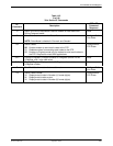
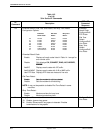
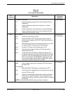
Table 14-3 lists all S-Registers supported by the 391x Series modems. The first column lists the
S-Register. The second column lists all possible values for that register. The third column lists the
key sequence used to enter the equivalent from the DCP. Use this column to reference commands
in Chapter 5, DCP Configuration, if further description is necessary.
NOTE
In some countries, the range of allowable values of some
S-Registers are restricted. If the DTE attempts to enter an illegal
value, the modem will answer OK, but it will set the register to the
closest legal value. The DTE can check the actual value of the
register with Sn? command.


