


Diagnostics and Troubleshooting
6-14
8000-A2-GB26-10
January 1999
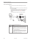
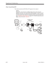
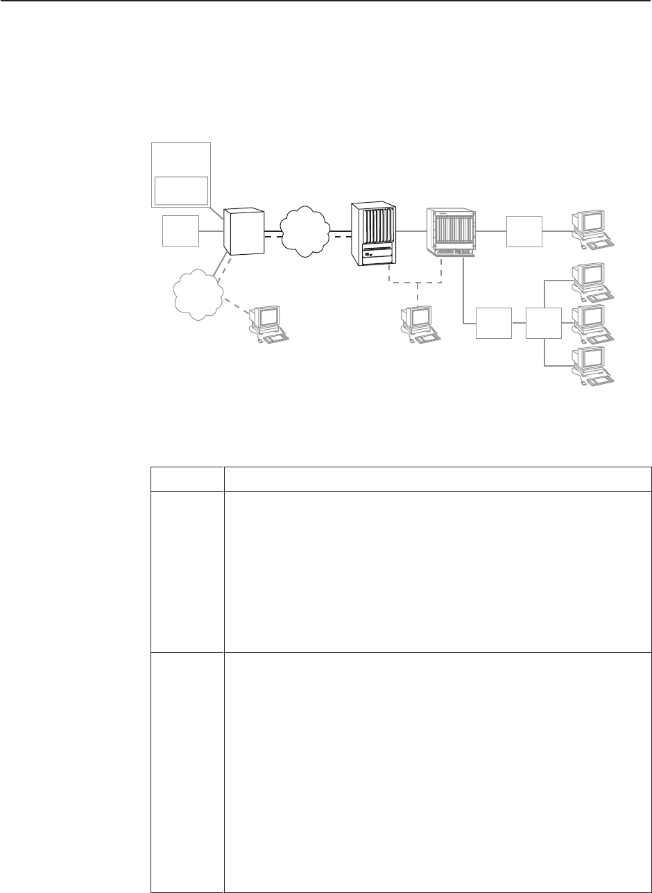
Client Cannot Reach Router
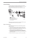
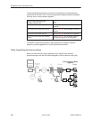
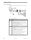
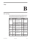
Table 6-7 examines the IPC-to-Router segment of the network on the IPC end of
the segment.
99-16175-01
OO
II
Next Hop
Router
(NHR)
DSLAM
Clients
NMS
WAN
HubSN
SN
ISP
IPC
WAN
IPC-to-Router
Segment
NMS
ISP
Gateway
Router
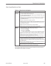
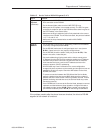
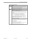
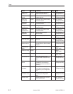
Table 6-7. IPC-to-Router Segment
Layer
Solution
Layer 1 –
Physical
1. On the IPC, make sure the cables are firmly attached to the WAN
interface.
2. If no CSU/DSUs are being used, either the router or the IPC must
provide network clocking. Network clocking is usually provided by the
device connected to the DCE cables.
3. If no CDU/DSUs exist between IPC and Router, make sure transmission
lines are active by looking for appropriate LEDs.
4. If there is no connection between the router and IPC, invert the clocking
on one or both DSU/CSUs.
Layer 2 –
Network
On the IPC:
1. Set payload scramble to false. To turn PLScramble on or off on the IPC,
type map slot/port (where slot/port is that of the ATM card) and set
10=1 to false.
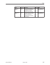
2. If using SONET, make sure that the line characteristics are correct.
Type map slot/port and select the Phy Media option.
3. Enter vas to make sure a service is configured.
4. Make sure encapsulation is the same as on the router (RFC1483).
5. Enter vvc to make sure vpi and vci are configured correctly.
6. Enter vcs to view ATM connection statistics.
7. Enter vcrs and vcts to view transmitted and received cells.