


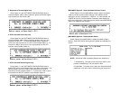
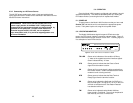
4.2 CONNECTION TO THE SERIAL PORT
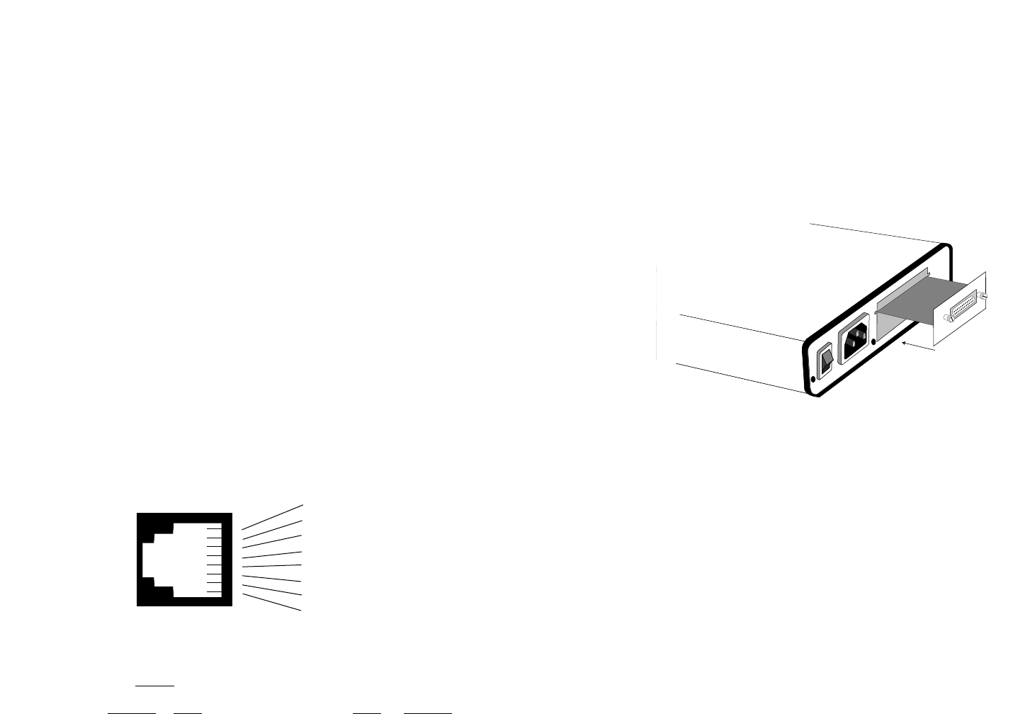
The serial port interface on the Model 1092 uses interchangeable
QuikConnect™
Modules. Each
QuikConnect™
Module has a 50-pin
card edge connector on one side and a serial port interface on the
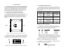
other. Figure 4 below shows how a
QuikConnect™
Module plugs into
the back of the Model 1092.
4.2.1 Changing
QuikConnect™
Modules
When you purchase a particular version of the Model 1092, it
should be shipped to you with the appropriate
QuikConnect™
Module
already installed. If you need to install a different
QuikConnect™
Module, follow these steps:
Removing the Existing
QuikConnect™
Module
1) Turn the power switch off. Leave the power cord plugged into a
grounded outlet to keep the unit grounded.
2) Loosen the two thumbscrews on the module by turning them
counterclockwise.
3) Grasp the two thumbscrews and gently pull the module from the
unit. Apply equal force to the thumbscrews to keep the module
straight during the removal process.
22
4.0 INSTALLATION
Once the Model 1092 is properly configured, it is ready to connect
to the twisted pair interface, to the serial port, and to the power source.
This section tells you how to make these connections.
4.1 CONNECTION TO THE TWISTED PAIR INTERFACE
The Model 1092 supports communication between two DTE
devices at distances to 5 miles (24 AWG) and data rates to 128 kbps
(sync) or 38.4 kbps (asynchronous). There are two essential
requirements for installing the Model 1092:
1. These units work in pairs. Therefore, you must have one Model
1092 (or a compatible model) at each end of a single twisted pair
interface.
2. To function properly, the Model 1092 needs one twisted pair of
metallic wire. This twisted pair must be unconditioned, dry,
metallic wire, between 19 and 26 AWG (the higher number gauges
may limit distance somewhat). Standard dial-up telephone circuits,
or leased circuits that run through signal equalization equipment,
or standard, flat modular telephone type cable, are not acceptable.
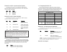
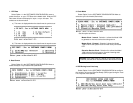
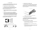
The RJ-45 connector on the Model 1092’s twisted pair interface is
pre-wired for a standard TELCO wiring environment. The signal/pin
relationships are shown in Figure 3 below.
Proper 2-W
ire Pairing between the two modems is as follows:
SIGNAL
PIN# PIN# SIGNAL
TIP 4 ----------------------------------------4 TIP
RING 5 ----------------------------------------5 RING
21
0 OFF
1 ON
Line
Interface Port
Figure 4. Installation of Model 1092 Plug-in Serial Interface Module
Figure 3. Model 1092 twisted pair line interface.
1 (N/C)
2 (N/C)
3 (N/C)
4 (Tip)
5 (Ring)
6 (N/C)
7 (N/C)
8 (N/C)
1
2
3
4
5
6
7
8