


3.0 CONFIGURATION
The Model 1092 is equipped with two sets of eight DIP switches,
which allow configuration of the unit to a wide variety of applications.
The Model 1092 is also equipped with an internal switch that allows
selection of 115 or 230 VAC power inputs (Note: this switch is not
present in Models 1092-UI and 1092-DC). This section describes
switch locations and explains all possible configurations.
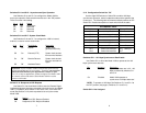
3.1 CONFIGURING THE HARDWARE DIP SWITCHES
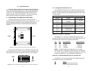
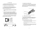
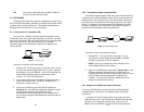
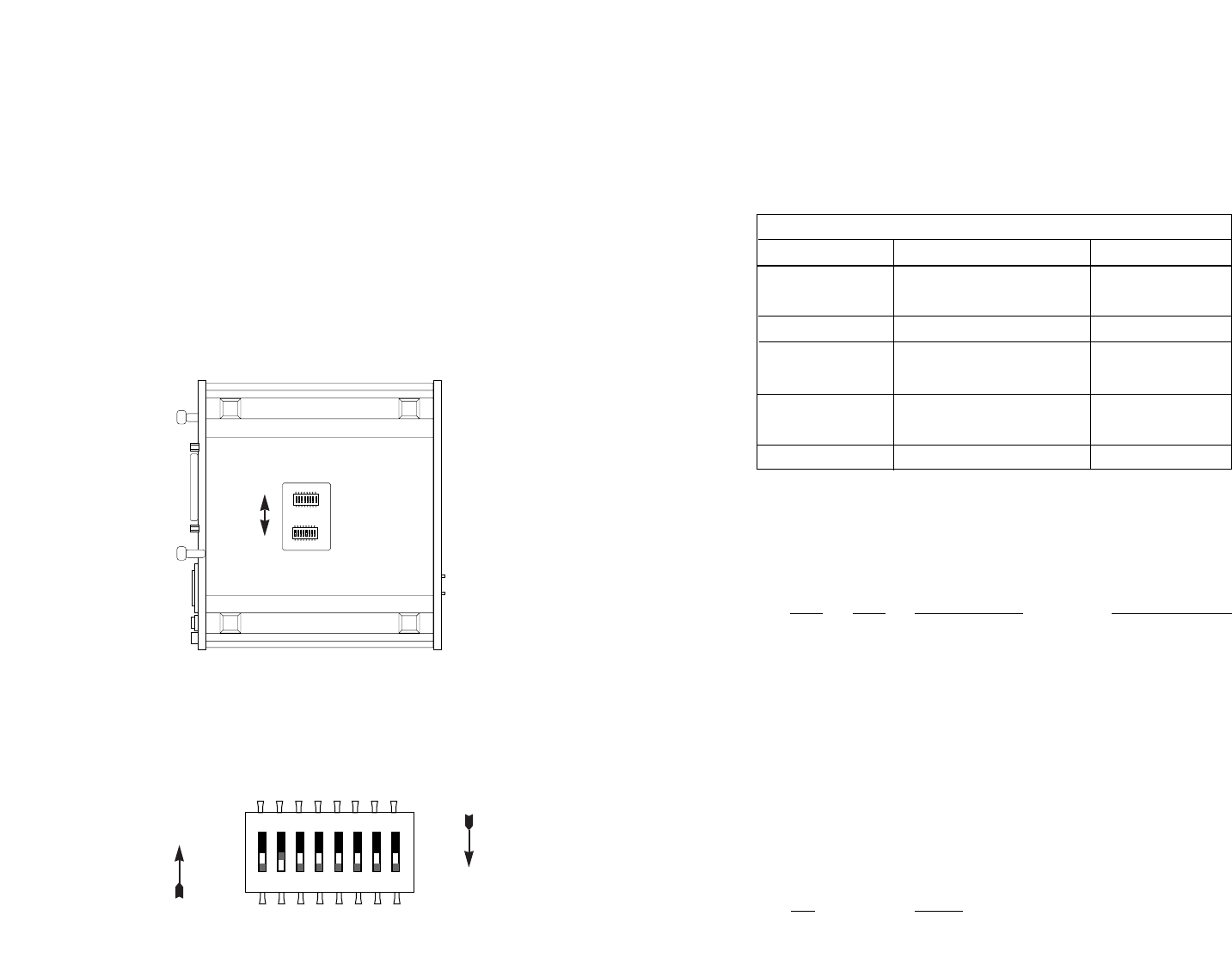
The Model 1092 uses a unique set of 16 external mini DIP
switches that allow configuration to wide range of applications. The 16
external switches are grouped into two eight-switch sets, and are
externally accessable from the underside of the Model 1092 (See
Figure 1).
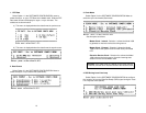
The two sets of DIP switches on the underside of the Model 1092
will be referred to as S1 and S2. Figure 2 shows the orientation of all
DIP switches is the same with respect to “ON” and “OFF” positions.
5
3.1.1 Configuration DIP Switch Set “S1”
The configuration switches on S1 set data rate, asynchronous or
synchronous data format, transmit clock source and response to RDL
request. The default settings and detailed descriptions for each switch
are shown below.
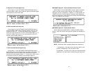
Switches S1-1 and S1-2: Data Rate
Use Switches S1-1 and S1-2 to configure the asynchronous or
synchronous data rate of the Model 1092. Each setting represents one
synchronous data rate and one asynchronous data rate.
S1-1
S1-2 Sync Data Rate Async. Data Rate
On On 32 Kbps Reserved
Off On 56 Kbps Reserved
On Off 64 Kbps Reserved
Off Off 128 Kbps 0 - 38.4 kbps
NOTE: The Model 1092 can also operate at the 19.2 kbps
synchronous rate. To operate at 19.2 synchronous, set Switches
S1-1 and S1-2 both to the OFF position and Switch S2-1 to the ON
position (see Section 3.2.1 for a description of Switch S2-1).
Switch S1-3: Data Set Ready During Line Loopback Test
Use Switch S1-3 to control the behavior of the DSR signal at the
EIA interface during the line loopback test.
S-3 Setting
On DSR is on during local line loop
Off DSR is off during local line loop
6
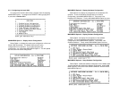
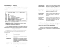
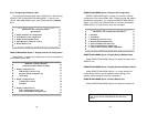
S1 SUMMARY TABLE
Position Function Factory Default
S1-1 Data Rate On
S1-2 Data Rate Off
S1-3 DSR during Local Line Loop On DSR On
S1-4 Async/Sync Data Format Off
S1-5 Async/Sync Data Format Off
S1-6 Tx Clock Source On
S1-7 Tx Clock Source On
S1-8 Response to RDL Request On Enable
64K Sync
}
}
Async/Sync
Internal Clock
}
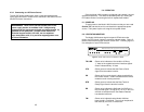
Figure 2. Close Up of Configuration Switches (both sets are identical in appearance)
ON
12345678
ON
12345678
ON
12345678
Figure 1. Underside of Model 1092, Showing Location of DIP Switches
Front
Back
S2
S1
ON
OFF
ON
OFF