


Installing the New
QuikConnect™
Module
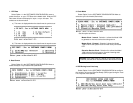
1) Make sure the power switch is off. Leave the power cord
plugged into a grounded outlet to keep the unit grounded.
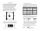
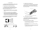
2) Hold the module with the faceplate toward you and align the
module with the guide slots in the rear panel of the Model 1092.
3) While keeping the module’s faceplate parallel with the Model
1092 rear panel, slide the module straight in–so that the card
edge contacts line up with the socket inside the chassis.
NOTE: The card edge connector should meet the socket when
it is almost all the way into the chassis. If you encounter a lot of
resistance, remove the module and repeat steps 2 & 3.
4) With the card edge contacts aligned with the socket, firmly seat
the module by using your thumbs to apply pressure directly to
the right and left edges of the module faceplate. Applying
moderate and
even
pressure should be sufficient to seat the
module. You should hear it “click” into place.
5) To secure the module in place, push the thumbscrews into the
chassis and turn the screws clockwise to tighten.
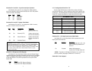
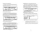
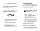
4.2.2 Connection to a “DTE” Device
The serial port on most
QuikConnect™
interface modules (all
except the X.21 module) is hard-wired as a DCE. Therefore these
modules “want” to plug into a DTE such as a terminal, PC or host.
When making the connection to your DTE device, use a straight
through cable of the shortest possible length—we recommend 6 feet
or less. When purchasing or constructing an interface cable, please
refer to the pin diagrams in Appendix D as a guide.
4.2.3 Connection to a “DCE” Device
If the Model 1090’s
QuikConnect™
interface module is hard-wired
as a DCE (all except the X.21 module), you must use a
null modem
cable when connecting to a printer, modem, multiplexer or other DCE
device. This cable should be of the shortest possible length—we
recommend 6 feet or less. When purchasing or constructing a null
modem interface cable, use the pin diagrams in Appendix D as a
guide.
NOTE: Pin-out requirements for null modem applications vary
widely between manufacturers. If you have any questions about a
specific application, contact Patton Technical Support.
23
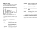
4.2.4 Configuring the X.21
QuikConnect™
Module
The serial port on the X.21
QuikConnect™
Module is default wired
as a DCE, but may be switched to a DTE. This is done by reversing
the orientation of the DCE/DTE strap, as described below:
To reverse DCE/DTE orientation, remove the module according to
the instructions in Section 4.2.1. The DCE/DTE strap is located on the
bottom side of the module’s PC board. The arrows on the top of the
strap indicate the configuration of the X.21 port (for example, if the DCE
arrows are pointing toward the DB-15 connector, the X.21 port is wired
as a DCE). Reverse the DCE/DTE orientation by pulling the strap out
of its socket, rotating it 180º, then plugging the strap back into the
socket. You will see that the DCE/DTE arrows now point in the
opposite directions, showing the new configuration of the X.21 port.
Reinstall the module according to the instructions in Section 4.2.1.
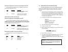
4.3 POWER CONNECTION
The Model 1092 is available with three power supply options:
Standard AC Power Supply option (Model 1092, no suffix) is
switchable between 100 and 253 VAC and is available with a
variety of domestic and international power cords. (See Appendix C).
Universal Interface AC Power Supply option (Model 1092-UI)
operates in environments ranging from 100 to 253 VAC, with no re-
configuration necessary (see Appendix C for available domestic and
international power cords).
DC Power Supply option (Model 1092-DC) operates in 48 VDC
environments and is equipped with a 3-pin “terminal strip” style
connector.
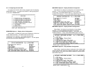
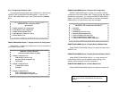
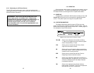
4.3.1 Connecting to an AC Power Source
The two AC power supply options–Standard and Universal–are
equipped with a male IEC-320 power connection. A domestic (US)
power supply cord is supplied with the unit at no extra charge. To
connect the standard or universal power supply, follow these steps:
1) Attach the power cord (supplied) to the shrouded male IEC-320
connector on the rear of the Model 1092.
2) Plug the power cord into a nearby AC power outlet.
3) Turn the rear power switch ON.
24