


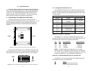
NS Glow red to indicate that the local Model 1092 has
not yet connected with the remote
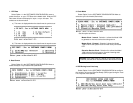
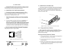
5.3 TEST MODES
The Model 1092 offers two proprietary loopback test modes, plus a
built-in V.52 BER test pattern generator, to evaluate the condition of the
modems and the communication link. These tests can be activated
physically from the front panel, or via the interface.
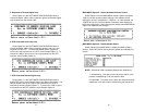
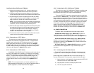
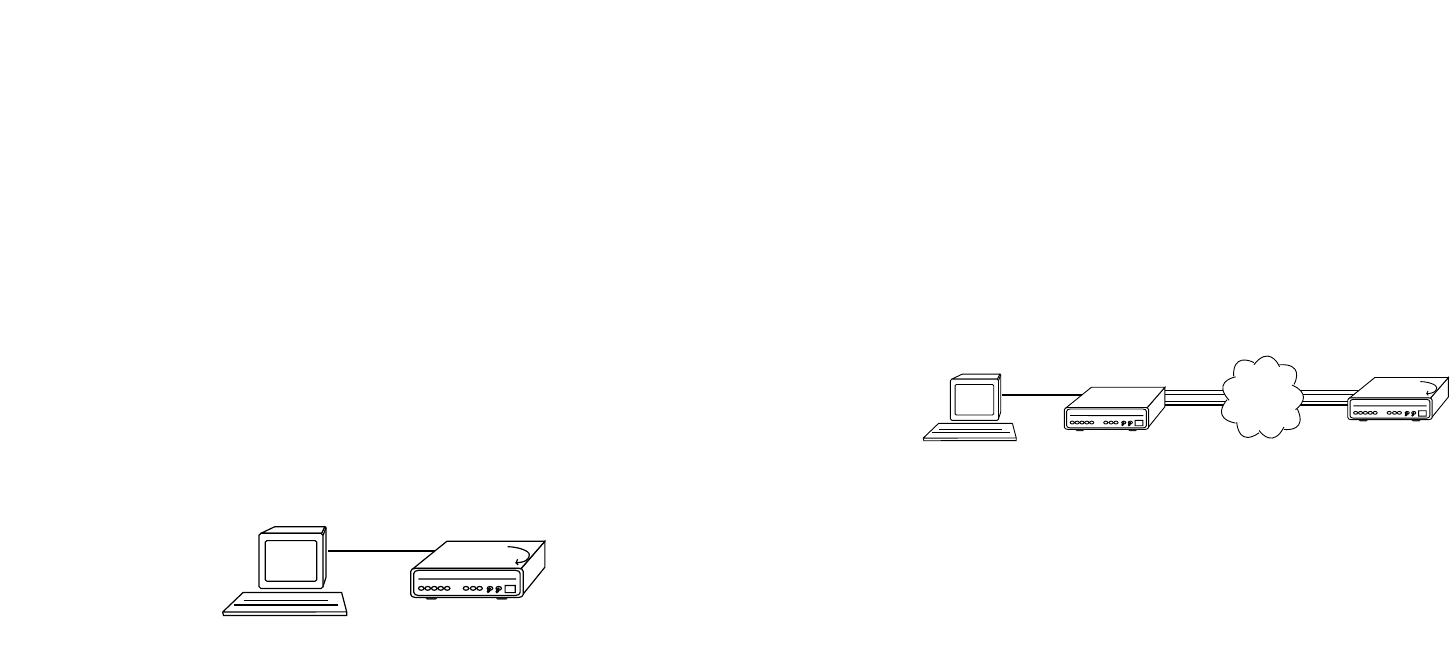
5.3.1 Using Local Line Loopback (LLB)
The Local Line Loopback (LLB) test checks the operation of the
local Model 1092, and is performed separately on each unit. Any data
sent to the local Model 1092 in this test mode will be echoed (returned)
back to the user device. (See Figure 6, below.) For example,
characters typed on the keyboard of a terminal will appear on the
terminal screen.
To perform a LLB test, follow these steps:
1. Activate LLB. This may be done in one of two ways: First, by
moving the front panel toggle switch UP to “Local”. Second,
by raising pin 18 on the interface. Once LLB is activated, the
Model 1092 transmitter output is connected to its own
receiver. The “TM” LED should be lit.
2. Verify that the data terminal equipment is operating properly
and can be used for a test. If a fault is indicated, call a
technician or replace the unit.
3. Perform a V.52 BER (bit error rate) test as described in
Section 5.3.3. If the BER test equipment indicates no faults,
but the data terminal indicates a fault, follow the
manufacturer’s checkout procedures for the data terminal.
Also, check the interface cable between the terminal and the
Model 1092.
27
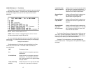
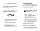
5.3.2 Using Remote Digital Loopback (RDL)
The Remote Digital Loopback (RDL) test checks the performance
of both the local and remote Model 1092s, and the communication link
between them. Any characters sent to the remote Model 1092 in this
test mode will be returned back to the originating device (see Figure 7,
below). For example, characters typed on the keyboard of the local
terminal will appear on the local terminal screen after having been
passed to the remote Model 1092 and looped back.
To perform an RDL test, follow these steps:
1. Activate RDL. This may be done in two ways: first, by
moving the front panel toggle switch DOWN to “Remote”.
Second, by raising pin 21 on the interface.
NOTE: Switch S1-8 (Response to RDL Request) on the
remote Model 1092 must be enabled.
2. Perform a V.52 BER test as described in Section 5.3.3. If the
BER test equipment indicates a fault, and the Local Line
Loopback test was successful for both Model 1092s, you may
have a problem with the twisted pair line between the
modems. You should then check the twisted pair line for
proper connections and continuity.
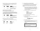
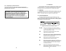
5.3.3 Using the V.52 (BER) Test Pattern Generator
To use the V.52 BER tests in conjunction with the Remote Digital
Loopback tests (or with Local Line Loopback tests), follow these
instructions:
1. Locate the “511/511E” toggle switch on the front panel of the
1092 and move it UP. This activates the V.52 BER test mode and
transmits a “511” test pattern into the loop. If any errors are
present, the local modem’s red “ER” LED will blink sporadically.
28
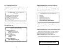
Figure 6. Local Line Loop
Local 1092
Figure 7. Remote Digital Loop