


Powering Up Your 1001R14 Rack
The power supplies that come with your 1001R14 rack system
are equipped with a power entry connector on the rear card. The
power supplies are
Hot-Swappable
, so you are not required to
remove the cards from the rack while applying power to the sys-
tem.
The power switch is located on the front panel. When plugged in
and switched on, a red front panel LED will glow. Since the Model
1001R14 is a "hot swappable" rack,
it is not necessary for any cards to
be installed before switching on the power supply
. The power supply
may be switched off at any time without harming the installed cards.
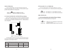
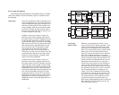
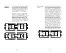
4.2 INSTALLING MODEL 1095RC SERIES INTO THE CHASSIS
The Model 1095RC Series is comprised of a front card and a rear
card. The two cards meet inside the rack chassis and plug into each
other by way of mating 50 pin card edge connectors. Use the follow-
ing steps as a guideline for installing each Model 1095RC Series into
the rack chassis:
1. Slide the rear card into the back of the chassis along the
metal rails provided.
2. Secure the rear card using the metal screws provided.
3. Slide the front card into the front of the chassis. It should
meet the rear card when it’s almost all the way into the chas-
sis.
4. Push the front card
gently
into the card-edge receptacle of the
rear card. It should “click” into place.
5. Secure the front card using the thumb screws.
4.3 WIRING THE MODEL 1095RC SERIES
Each of the rear interface cards compatible with the Model
1095RC Series has one terminal interface port and one 2-wire (twisted
pair) port. For specific interface pin-outs, refer to the diagrams in
Appendix C and E of this manual.
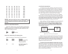
4.0 INSTALLATION
This section describes the functions of the Model 1001R14 rack
chassis, tells how to install front and rear Model 1095RC Series cards
into the chassis, and how to connect to the twisted pair interface and
the serial interface.
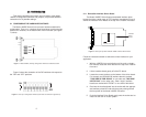
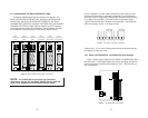
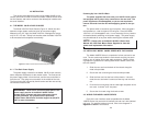
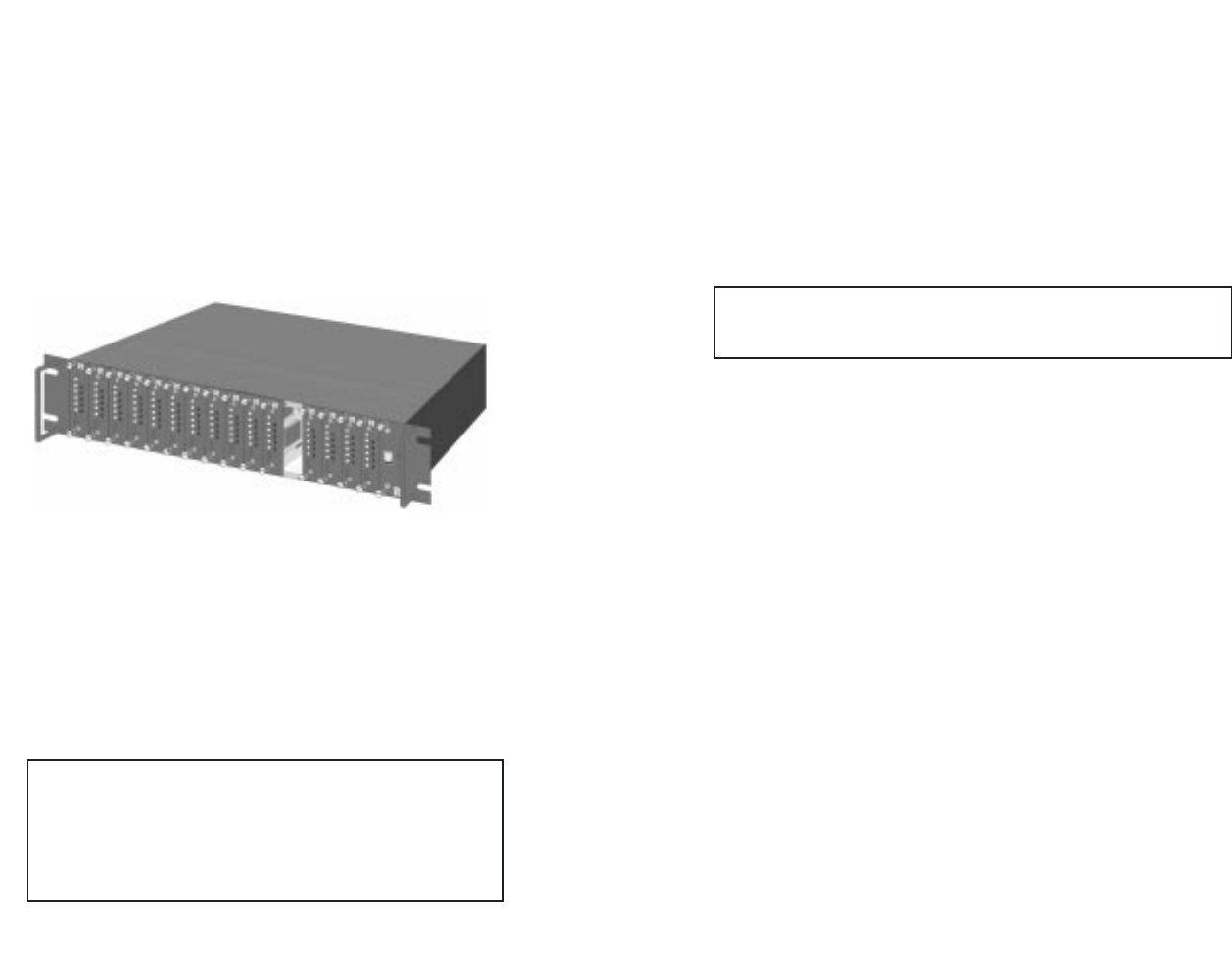
4.1 THE MODEL 1001R14 RACK CHASSIS
The Model 1001R14 Rack Chassis (Figure 10, below) has four-
teenshort range modem card slots, plus its own power supply.
Measuring only 3.5” high, the Model 1001R14 is designed to occupy
only 2U in a 19” rack. Sturdy front handles allow the Model 1001R14
to be extracted and transported conveniently.
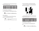
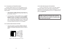
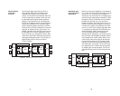
4.1.1 The Rack Power Supply
The power supply included in the Model 1001R14 rack uses the
same mid-plane architecture as the modem cards. The front card of
the power supply slides in from the front, and the rear card slides in
from the rear. They plug into one another in the middle of the rack.
The front card is then secured by thumb screws and the rear card by
conventional metal screws.
19
NOTE: Please refer to the Model 1001RP14 Series User
Manual
AC & DC Rack Mount Power Supplie
s for fuse and
power card replacement information.
20
Figure 10: Model 1001R14 Rack Chassis with power supply
WARNING! There are no user-serviceable parts in the
power supply section of the Model 1095RC Series.
Voltage setting changes and fuse replacement should
only be performed by qualified service personnel.
Contact Patton Electronics Technical support at (301)975-
1007 for more information.