


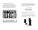
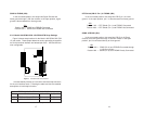

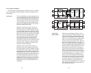
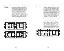
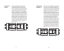
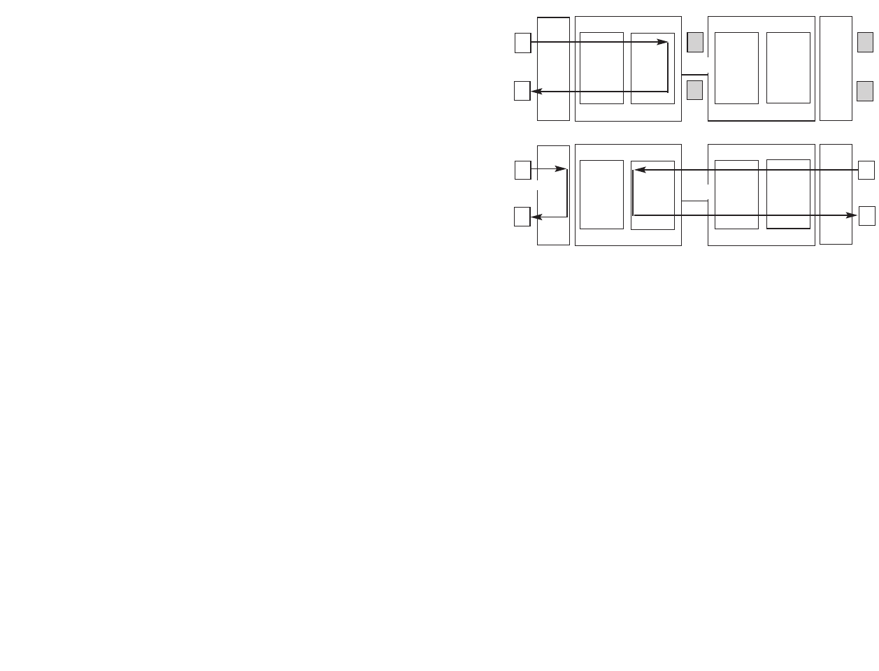
Figure 13. Block Diagram Local Loop Mode 1
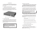
Figure 14. Block Diagram Local Loop Mode 2
Local Loop When the unit is placed into a Mode 1 Local
with 511/511E Loop and the 511/511E pattern generator is acti-
vated, the local pattern generator begins send-
ing out a 511/511E pattern to the Loop Control
block. The Loop Control block will loop this data
back to the 511/511E pattern detector block,
which will evaluate the data for errors. Because
the 511/511E pattern generator is contained
within the Processor the data is unframed so the
framer will begin seeing unframed packets. The
framer receives this unframed data and can not
distinguish this information from a line discon-
nection (this would cause the units' Restart pro-
cedure to start). What we have done to allow
this mode to work is to add time outs for the pat-
tern generators. When the 511/511E is initiated
the line restart procedure is changed to one
minute. The 511/511E pattern will timeout after
45 seconds. So if the 511/511E is turned on dur-
ing a local loop, the restart procedure is set to
one minute, but the 511/511E pattern will time-
out after 45 seconds, allowing the framer to
begin seeing framed packets (and not restart the
box). After the 511/511E pattern times out, the
ER led will begin flashing.
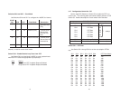
5.2.2 Loops and Patterns
The following section describes the Test Modes used in the Model
1095. At the bottom of each Test Mode, a figure is included to show
the data path.
Local Loop There are two different modes of operation for a
Local Loop depending on the status of the units
at the time that the Local Loop is initiated. If the
units are not linked (NS LED on) and the Local
Loop is initiated, either by the front panel switch
or the DTE interface, the unit will enter mode 1.
If the units are linked, NS LED off, then the unit
will enter a mode 2 Local Loop.
A Mode 1 Local Loop is shown in Figure 13.
When the Local Loop is initiated, either by the
front panel switch or the DTE interface, the loop
will be activated within the local DSP. The data
present at the local DTE interface will be looped
back to the local DTE by the Loop Control block
within the Processor. Any data present on the
line or at the far end DTE interface is invalid.
The remote unit will remain in the StartUP
mode, NS LED off, CTS LED yellow, and CD
LED yellow, until the local unit is taken out of the
LocalLoop mode. After the Local Loop is dese-
lected, the units will both be in StartUP mode
and the link will be established.
A mode 2 Local Loop is shown in Figure 14.
When the Local Loop is initiated, either by the
front panel switch or the DTE interface, two sep-
arate loop paths will be started. In the first path,
data presented to the local DTE interface will be
looped back to the local DTE within the framer.
In the second path data presented at the far end
DTE will be transmitted to the local DTE then
looped back within the local DTE Loop Control
block with the Processor. After the Local Loop is
deselected, the units will be placed back into
DataMode and the normal data paths will be re-
established.
27
Pattern
Gen/Det
Loop
Contr
ol
Loop
Contro
l
Pattern
Gen/Det
Processor
Processor
Framer
Framer
Line
Pattern
Gen/Det
Loop
Contr
ol
Loop
Contro
l
Pattern
Gen/Det
Processor
Processor
Framer
Framer
Line
28