


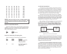


5.2.3 Using the V.52 (BER) Test Pattern Generator
To use the V.52 BER tests in conjunction with the Remote Digital
Loopback tests* (or with Local Line Loopback tests), follow these
instructions:
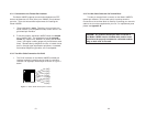
1. Locate the “511/511E” toggle switch on the front panel of the
1095RC and move it to the left. This activates the V.52 BER
test mode and transmits a “511” test pattern into the loop. If
any errors are present, the local modem’s red “ER” LED will
blink sporadically.
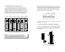
2. If the above test indicates no errors are present, move the
V.52 toggle switch to the right, activating the “511/E” test with
errors present. If the test is working properly, the local
modem's red “ER” LED will glow. A successful “511/E” test
will confirm that the link is in place, and that the Model
1095RC’s built-in “511” generator and detector are working
properly.
33
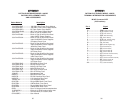
AAPPPPEENNDDIIXX AA
PATTON ELECTRONICS MODEL 1095RC
SPECIFICATIONS
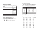
Transmission Format: Synchronous
Transmission Line: Two-Wire unconditioned twisted pair
Clocking: Internal, external or receive recovered clock
Interface Modules: EIA RS-232/ITU/T V.24, RS-232/530,
ITU/T V.35 and ITU/T X.21
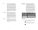
Line Rates: 144, 272, 400, 528, 784, 1040, 1552,
2064, and 2320 kbps
DTE Rates: 64, 128, 192, 256, 320, 384, 448, 512, 576,
640, 704, 768, 832, 896, 960, 1024, 1088,
1152, 1216, 1280, 1344, 1408, 1472, 1536,
1600, 1664, 1728, 1792, 1856, 1920, 1984,
2048, 2112, 2176, 2240, and 2304 kbps
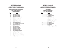
Diagnostics: V.52 compliant bit error rate pattern
(511/511E pattern) generator and detector
with error injection mode; Local Line
Loopback and Remote Digital Loopback,
activated by front panel switch or via serial
interface
LED Status Indicators: TD, RD, CTS, CD, DTR, NS(no signal), ER
(error) and TM (test mode)
Connectors: RJ-45 or Terminal Block on line side; DB-25
female, M/34 female or DB-15
female on serial interface side,
depending upon which interface module is
installed.
Power: 100-253 VAC, 50-60 Hz (universal input);
48 VDC (option). 10 watts.
Temperature Range: 32-122°F (0° -50°C)
Altitude: 0-15,000 feet
Humidity: 5 to 95% non-condensing
Dimensions: Front Card: 4.81” x 3.10” x 0.95”
(12.2 x 7.8 x 2.4cm)
Rear Card: 3.33” x 2.8” x 0.95”
(8.4 x 7.1 x 2.4cm)
Weight: Front Card: 0.22 lbs (.10Kg)
Rear Card (M/34 with V.35 interface): 0.16
lbs (.07Kg)
Rear Card (DB-25/RS-232 interface): 0.12
lbs. (.05Kg)
34
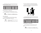
*NOTE: The above V.52 BER tests can be used independently
of the Remote Digital Loopback tests. This requires two opera-
tors: (1) to initiate and monitor the tests at the local Model
1095RC, and (2) to do the same at the remote Model 1095RC. In
this case, the test pattern sent by each Model 1095RC will not be
looped back, but will be transmitted down the line to the other
Model 1095RC.