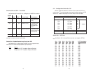
Off On On Off Off On 1472
On Off On Off Off On 1536
On On Off Off Off On 1600
Off On Off Off Off On 1664
On Off Off Off Off On 1728
Off Off Off Off Off On 1792
On On On On On Off 1856
Off On On On On Off 1920
On Off On On On Off 1984
Off Off On On On Off 2048
On On Off On On Off 2112
Off On Off On On Off 2176
On Off Off On On Off 2240
Off Off Off On On Off 2304
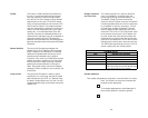
Switch S3-7: Reset Software Defaults
Switch S3-7 allows the user to reset the software configured facto-
ry defaults. This will only be needed when using the Model 1001MC to
SNMP manage your units. For more information, please refer to the
Model 1001MC Operations Manual.
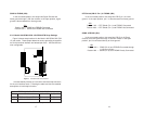
S3-7
Setting
On Normal Operation
Off Reset
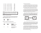
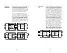
Switch S3-8: Transmit Data (TD) Sampling Point
Switch 3-8 controls the Transmit Data (TD) sampling point.
S3-8
Setting Description
On Normal TD sampled on the falling
edge of the 1095RC
Transmit Clock (TC)
Off Invert TD sampled on the rising
edge of the 1095RC
Transmit Clock.
11
12
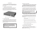
3.2 NETLINK PLUG-AND-PLAY
The NetLink Plug-and-Play application allows ISPs and PTTs to
quickly upgrade the link speed for a customer without re-configuring
the Customer Premise (CP) Model 1095. It will also allow ISPs and
PTTs to set up all of the configurations at the Central Office (on the
rack cards) before installation of the stand alone units, thus saving
time spent configuring and re-configuring DIP switch settings.
The NetLink Plug-and-Play feature allows the user to configure
the DTE rate for the link from the rack card at the Central Office (CO).
The stand alone unit at the Customer Premise (CP) site will automati-
cally configure itself to the DTE rate of the rack card. Other configura-
tion parameters fall to the default state. This allows changes in the
configuration to be handled from a single end of the link.
When installing a CO/CP style application, the local end of the link
is comprised of a CO unit (1095 or 1095RC) set to either Internal or
External clocking mode and a CP unit (1095 or 1095RC) set as a
NetLink Plug-and-Play CP.
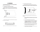
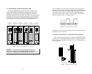
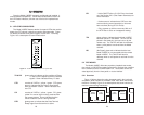
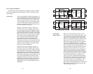
The NetLink Plug-and-Play CP stand
alone will have all of its DIP switches set to the ON position
(as
indicated below in Figure 4).
When the units are connected, the CP will come up with a prede-
fined default configuration (Receive Recovered Clocking). During the
handshaking process between the units, the CO unit will set the DTE
rate/line rate of the CP unit to match its DIP switch configuration set-
tings. If the DTE rate for the link requires a change, the change is
needed only at the CO side of the link.
The NetLink Plug and Play application will also work in the man-
aged system using the Model 1001MC and 1095RC cards installed in
Patton’s 2U rack system. In this application, the system administrator
can configure the entire rack through the Network Management Station
(NMS) before the stand alone (CP) units are installed. For more infor-
mation on the SNMP management of your rack, please refer to the
Model 1001MC Operations Manual.
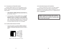
NOTE: Based on the DTE rate chosen, the Model 1095RC will
automatically select the optimum line rate for the distance. This
selection is based on the lowest line rate that will support the
DTE rate.
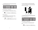
1095RC
(CO)
1095
(CP)
DIP Switches all in ONposition
DIP Switches configured according
to specific application requirements
Figure 4. Typical NetLink Plug-and-Play Application


