


16
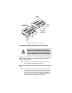
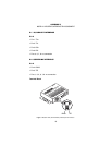
5.2 FRONT PANEL LED STATUS MONITORS
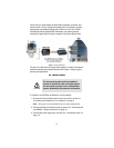
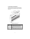
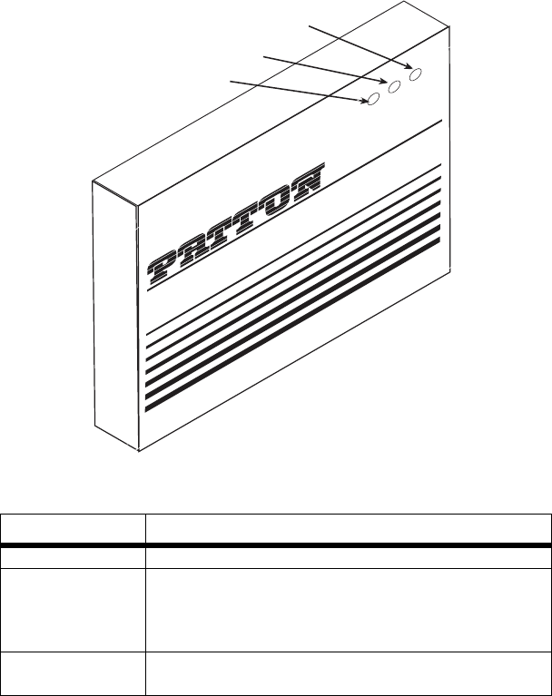
The Model 2172R features three front panel LEDs that monitor power,
the Ethernet signals, and the CopperLINK connection. Figure 8 shows
the front panel location of each LED. Table 8 on page 16 describes the
LED functions.
Figure 8.
Model 2172R standalone unit front panel
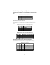
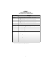
Table 8:
Front panel LED description
LED Description
Power Solid GREEN to indicate the unit is powered on.
Link Solid GREEN (ON) to indicate that the end-to-end
CopperLINK link between the Model 2172Rs is
established. The Link LED is OFF when the link is
down.
Ethernet Solid GREEN indicates that 10/100Base-T Ethernet
link has been established. Flashes to indicate activity.
Ethernet LED
Link LED
Power LED
Ethernet
Link
Power
CopperLink 2172
Ruggedized Ethernet Extender
L
in
k
P
o
w
e
r
5
V
; 0
.6
A
E
th
e
rn
e
t
R
e
m
L
o
c