


2
CONTENTS
1.0 Warranty Information ................................................................. 4
1.1 Compliance................................................................................... 4
EMC Compliance:......................................................................... 4
Safety Compliance: ...................................................................... 4
PSTN Compliance:....................................................................... 4
1.2 Radio and TV Interference (FCC Part 15) .................................... 5
1.3 CE Declaration of Conformity ....................................................... 5
1.4 Service.......................................................................................... 5
1.5 Safety When Working With Electricity .......................................... 6
2.0 General Information.................................................................... 7
2.1 Features........................................................................................ 7
2.2 Description.................................................................................... 7
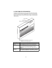
3.0 Installation................................................................................... 8
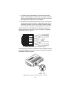
3.1 Connecting the Twisted-Pair Line Interface.................................. 9
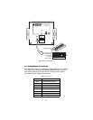
3.2 Connecting the 10/100Base-T Ethernet Interface ...................... 11
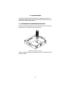
3.3 Connecting Power ...................................................................... 11
4.0 Configuration ............................................................................ 12
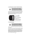
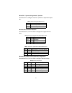
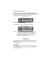
4.1 Configuring the hardware DIP switches...................................... 12
4.2 Configuring DIP Switch S2 ......................................................... 13
Switch S2-1: Symmetric/Asymmetric Operation......................... 14
Switches S2-2 and S2-3: Data Rate........................................... 14
5.0 Operation................................................................................... 15
5.1 Power Up.................................................................................... 15
5.2 Front Panel LED Status Monitors ............................................... 16
A
Specifications ........................................................................... 17
A.1 LAN Connection .......................................................................... 17
A.2 Transmission Line ....................................................................... 17
A.3 CopperLINK Line Rate and CopperLINK Distance .................... 17
A.4 CopperLINK Surge Suppressor .................................................. 17
A.5 LED Status Indicators ................................................................. 17
A.6 Power Supply .............................................................................. 17
A.7 Temperature Range .................................................................... 17
A.8 Humidity ...................................................................................... 17
A.9 Dimensions ................................................................................. 17
B
Model 2172R Series Factory
Replacement Parts and Accessories...................................... 18