


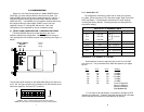
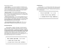
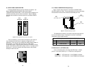
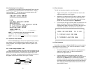
3.3 REAR CARD CONFIGURATION
The Model 2500RC Series has two interface card options: the
Model 1000RCM12548 (DB-25/RJ-48S) and the Model
1000RCM13448 (M/34/RJ-48S). Each of these options supports one
interface connection and one 4-wire connection. Figure 5 (below)
illustrates the two different interface options for the Model 2500RC
Series.
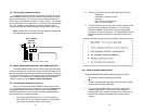
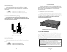
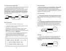
Prior to installation, you will need to examine the rear card you
have selected and make sure it is properly configured for your
application. Each rear card is configured by setting straps located on
the PC board. To configure the rear cards, you must set the
configuration straps. Figure 6 (below) shows the orientation of these
straps. Each strap can either be on pegs 1 and 2, or on pegs 2 and 3.
Sections 3.3.1 and 3.3.2 describe the strap locations and possible
settings for each rear card.
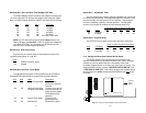
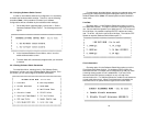
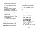
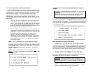
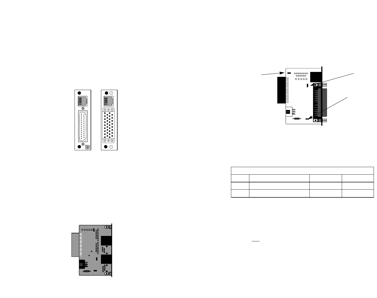
3.3.1 Model 1000RCM12548 Strap Settings
Figure 7 shows strap locations for the Model 1000RMC12548
(DB-25/RJ-48S) rear cards. These straps determine various grounding
characteristics for the terminal interface and twisted pair lines.
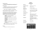
The table below provides an overview of interface strap functions
for the rear interface cards. Following this overview is a detailed
description of each strap’s function.
DTE Shield (Pin 1) & FRGND (JB3)
In the connected position, this strap links DB-25 pin 1 & frame
ground. In the open position, pin 1 is “lifted” from frame ground.
JB3
Position 1&2 = DTE Shield (Pin 1) and FRGND Connected
Position 2&3 = DTE Shield (Pin 1) and FRGND Not Connected
23
24
Figure 7. DB-25/RJ-48S strap locations
JB2
(NOT USED)
JB3
(peg 1 on top)
JB4
(peg 1 on left)
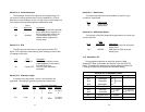
INTERFACE CARD STRAP SUMMARY TABLE #1
Strap Function Position 1&2 Position 2&3
JB3 DTE Shield (Pin1) & FRGND Connected Open*
JB4 FRGND & SGND Connected Open*
Figure 5. Model 2500RC Series interface card options
DB-25 F
M/34 F
Model
1000RCM12548
Model
1000RCM13448
Figure 6. Orientation of interface card straps