


31 32
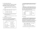
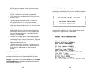
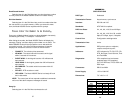
5.2.2 Displaying Line/Loop Status
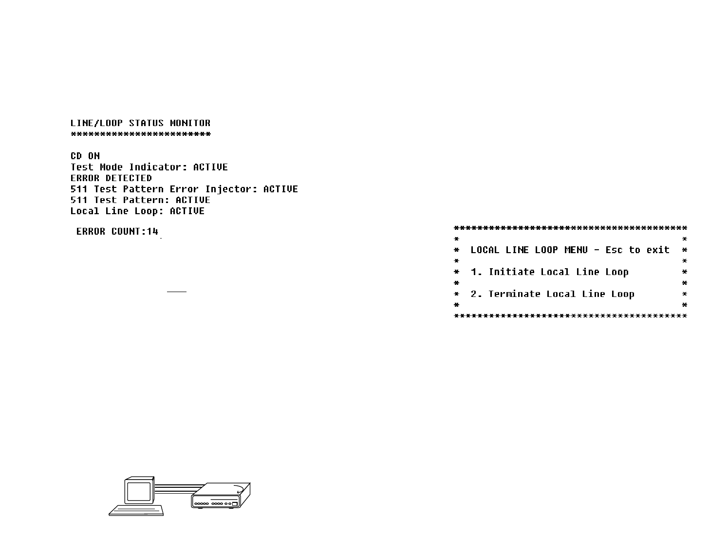
To check the current status of the Model 2500RC Series and the
associated circuit, go to the Main Menu and select item 4, “Display
Line/Loop Status”
1,2
. This will take you to a screen similar to the
Line/Loop Status Monitor Screen (below).
NOTE
1
: To refresh the display with the most up-to-date
information, key “4” and press [RETURN].
NOTE
2
: The error count is reset after each time it is displayed.
5.3 LOOPBACK TEST MODES
The Model 2500RC Series offers three loopback tests to evaluate
the condition of the CSU/DSUs and the communication link: local
analog loopback, remote digital loopback and telco loopback (C.O.
Loopback).
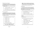
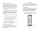
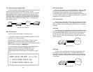
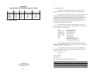
5.3.1 Local Analog Loopback (LAL)
The Local Analog Loopback (LAL) test checks the operation of the
local Model 2500RC Series. Any data sent to the local Model 2500RC
Series in this test mode will be echoed (returned) back to the user
device. For example, characters typed on the keyboard of a terminal
will appear on the terminal screen (see Figure 11, below).
LAL Test Activation
The LAL test may be activated in one of three ways:
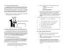
1. Toggle the front panel “Local/Normal/Remote” switch to the
right hand side to the “Local” position.
2. Activate the LL lead from the DTE (Note: in order to use this
option, the DTE Loop Control option must be enabled–see
Section 3.2.4). If you are not sure which pin is the LL lead,
please refer to the pinout diagrams in Appendix D.
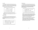
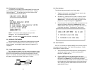
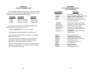
3 From a terminal, first go to the Main Menu and select item 3 to
display the Software Switch Menu (Section 3.2.4) In the
Software Switch Menu, select item “e” to go to the Local Line
Loop Menu (see below). To activate LAL, select item 1.
LAL Test Procedure
Once LAL is activated, the Model 2500RC Series transmit output is
connected to its own receiver. The “Test” LED should be lit. Follow
these steps to complete the test:
1. Verify that the data terminal equipment is operating properly
and can be used for a test. If a fault is indicated, call a
technician or replace the unit.
2. Perform a BER (bit error rate) test on each unit using a
separate BER tester (The Model 2500RC Series has a built-in
BER tester–see Section 5.4). If the BER test equipment
indicates no faults but the data terminal indicates a fault, follow
the manufacturer's checkout procedures for the data terminal.
Also, check the interface cable between the terminal and the
Model 2500RC Series.
CSU/DSU
Figure 11. Local analog loop