


27 28
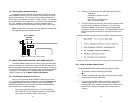
Switching the Power Supply On and Off
The power switch is located on the front panel. When plugged in
and switched on, a red front panel LED will glow. Since the Model
1000R16 is a "hot swappable" rack,
it is not necessary for any cards to
be installed before switching on the power supply
. The power supply
may be switched off at any time without harming the installed cards.
NOTE: Please refer to the Model 1000RP Series User Manual
AC
and DC Rack Mount Power Supplie
s for fuse and power card
replacement information.
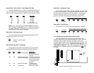
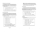
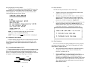
4.2 INSTALLING THE MODEL 2500RC SERIES INTO THE CHASSIS
The Model 2500RC Series is comprised of a front card and a rear
card. The two cards meet inside the rack chassis and plug into each
other by way of mating 50 pin card edge connectors. Use the following
steps as a guideline for installing each Model 2500RC Series into the
rack chassis:
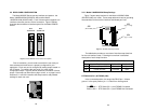
1. Slide the rear card into the back of the chassis along the metal
rails provided.
2. Secure the rear card using the metal screws provided.
3. Slide the card into the front of the chassis. It should meet the
rear card when it’s almost all the way into the chassis.
4. Push the front card
gently
into the card-edge receptacle of the
rear card. It should “click” into place.
5. Secure the front card using the thumb screws.
NOTE: Since the Model 1000R16 chassis allows “hot
swapping” of cards, it is
not necessary to power down
the rack
when you install or remove a Model 2500RC Series.
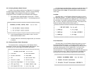
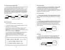
4.3 WIRING THE MODEL 2500RC SERIES
Each of the rear interface cards compatible with the Model 2500RC
Series has one terminal interface port and one 4-wire (twisted pair)
port. For specific interface pin-outs, refer to the diagrams in
Appendix D of this manual.
5.0 OPERATION
Once the Model 2500RC Series unit is installed and configured
properly it is ready to operate. This section describes the function of
the LED indicators, the status displays, the use of loopback test modes,
and Switched 56 dialing procedures (Models 2510RC and 2520RC
only).
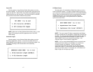
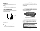
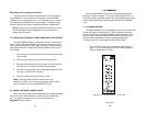
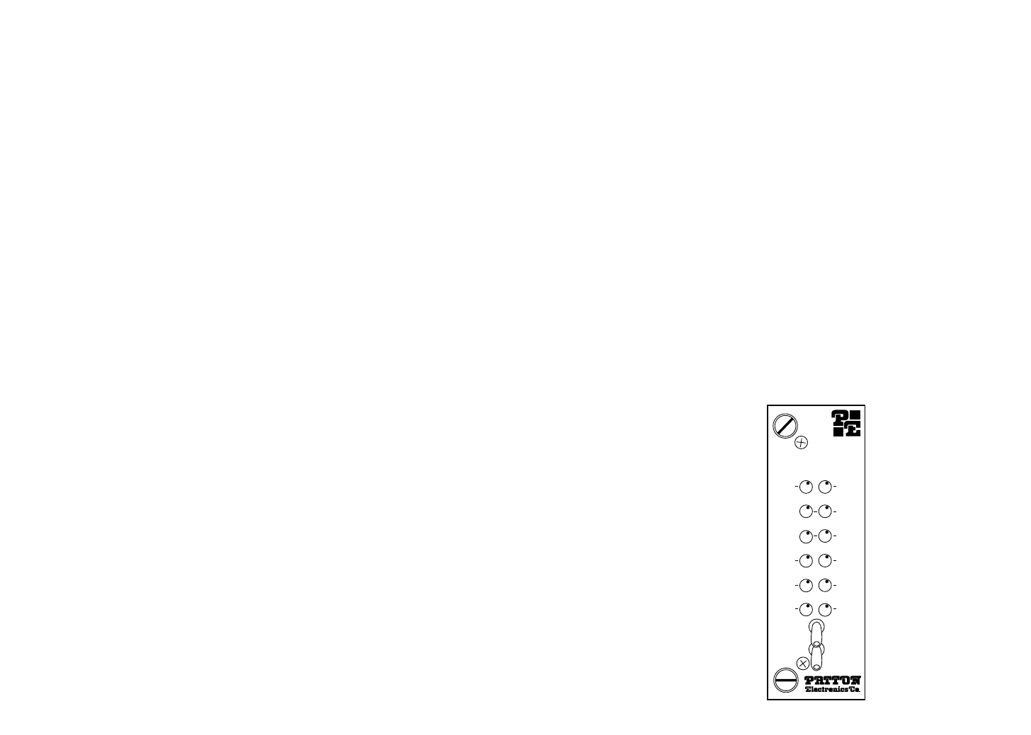
5.1 LED DESCRIPTIONS
The Model 2500RC Series is equipped with nine LED indicators that
monitor the status of communication. Figure 12 (below) shows the
location of the LEDs on the Model 2500RC Series front panel. Note
also the location of the test mode switches and RS-232 control port
(used in Switched 56 dialing as well as software configuration).
Following Figure 12 is a description of each LED’s function.
• “TD” and “RD” will glow red to indicate an Idle condition or
Binary “1” data on the respective terminal interface signals.
Green indicates Binary “0” data.
(continued)
Figure 10. The Model 2500RC Series' front panel LEDs
Model 2500RC
Power
TD
RD
OS
CTS
ER
Analog
511
Remote
511/E
CD
NS
TM
DTR