


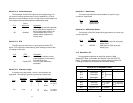
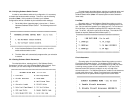
Switches S2-1, S2-2 and S2-3: Rate Adapter/DTE Rate
The Model 2500RC Series includes a rate adapter that allows the
unit to be used with DTE devices that support rates lower than 56/64
kbps. All switch settings below are valid for line rates of 56 or 64 kbps.
S2-1 S2-2 S2-3 DTE Rate
On On On 2.4 kbps
Off On On 4.8 kbps
On Off On 9.6 kbps
Off Off On 19.2 kbps
On On Off 38.4 kbps
Off Off Off Line Rate = DTE Rate
NOTE: for DTE devices that operate at 57.6 kbps, set the Line
Rate to 56 kbps (see Section 3.1.1 4.1.1), set the rate adapter for
“Line Rate=DTE Rate”, and configure your DTE device for two
stop bits (set character length accordingly).
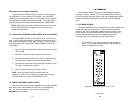
Switch S2-4: DTE Loop Control
The local loop and remote loop can be activated from the DTE
interface using signals “LL” and “RL”.
S2-4
On Enable LL and RL inputs
Off Disable
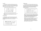
Switches S2-5 and S2-6: Clock Mode
The appropriate transmitter clocking modes can be selected for
Dedicated DDS, Switched-56 or campus-area (private) operation.
S2-5 S2-6 Mode Description
On Off External Clock Mode Transmit Clock
derived from terminal
interface
Off Off Network Clock Mode Transmit clock derived
(Looped Clock Mode) from the received line
signal; Use this mode
for Dedicated DDS
operation
On On Internal Clock Mode Transmit Clock
derived internally
Off On Switched 56 (Model 2510, 2520)
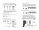
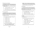
Switch S2-7: Anti-Stream Timer
The anti-stream timer protects multidrop networks from a drop that
is continuously transmitting. If the terminal keeps RTS raised for more
than 30 seconds, the timer forces RTS off internally. This allows the
rest of the multidrop network to resume operation. The CSU/DSU
remains in the forced-off condition until the terminal drops RTS.
T
imer Value in Sec at Various Line Rates
S2-7 Timer 56 19.2 9.6 4.8 2.4
On Disabled
Off Enabled 2 4 8 15 30
Switch S2-8: RTS/CTS Delay
The RTS/CTS turn-on delay can be set to Normal or Extended.
Delay in mSec at V
arious Line Rates
S2-8 CTS Delay 56 19.2 9.6 4.8 2.4
Off Normal 0.3 0.9 1.9 3.8 7.5
On Extended 1.3 3.8 7.5 15 30
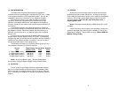
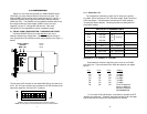
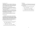
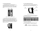
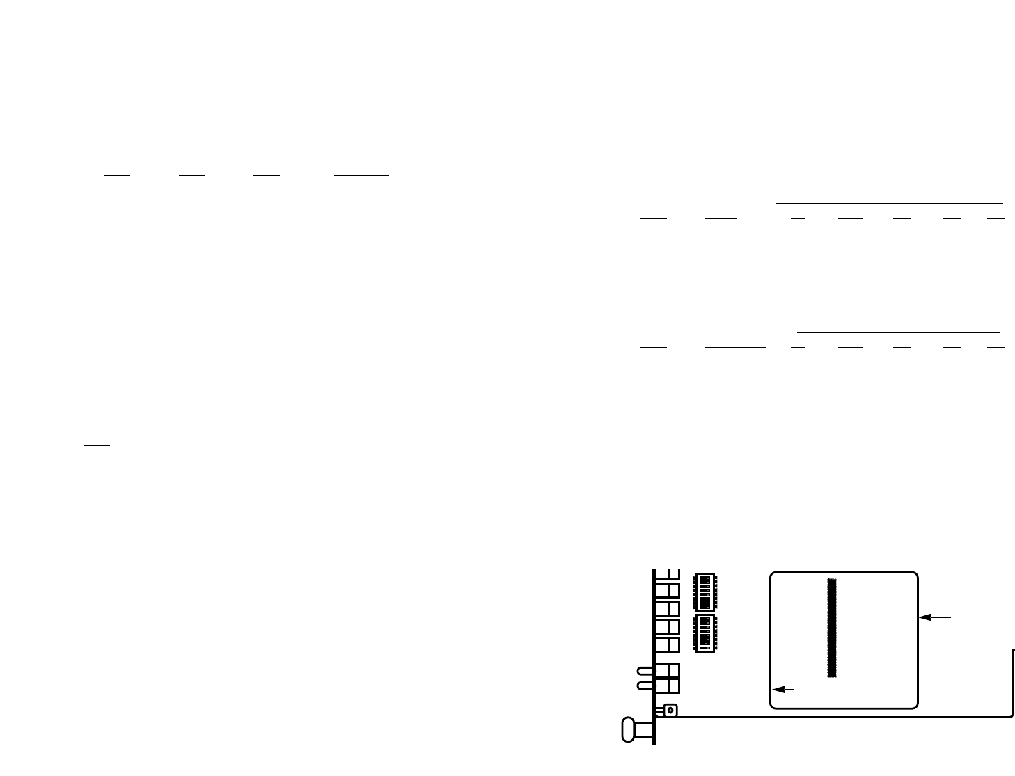
3.1.3 Setting the Reversible Interface Driver Board
The Model 2500RC Series supports both RS-232 and V.35
electrical interfaces for the terminal connection port. Which electrical
interface is active is determined by the orientation of the small
reversible daughter board on the front card (see Figure 3, below). The
daughter board is clearly marked “THIS SIDE UP FOR RS-232” and
“THIS SIDE UP FOR V.35”. Note: When plugging the daughter board
into the socket, the arrow should always point toward the front
of the
PC board.
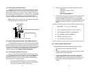
1211
Figure 3. Closeup of Model 2500RC Interface Driver Board
ON
12345678
ON
12345678
Interface
Driver
Board
FRONT THIS SIDE UP FOR V.35