


35 36
5.4 THE V.52 BER TEST PATTERN GENERATOR
The Model 2500RC Series has a built-in test pattern generator and
detector. It can be invoked at both ends of a link simultaneously (using
two operators) or it can be invoked in conjunction with the LAL or RDL
tests (using one operator). The following example requires two
operators–one to initiate and monitor the test at the local Model
2500RC Series, and one at the remote Model 2500RC Series. To use
the V.52 BER test by itself, both operators should
simultaneously
follow
these steps:
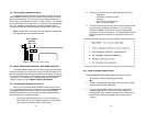
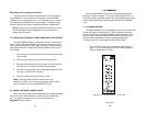
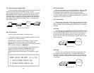
1. Locate the “511/511E” toggle switch on the front panel of the
Model 2500RC Series and move it to the left hand side (see
Note 1). This activates the V.52 BER test mode and transmits
a “511” pseudorandom test pattern to the other unit. If any
errors are received, the receiving CSU/DSU’s red “Error” LED
will blink sporadically (see Notes 1 & 2, below).
2. If the test indicates no errors are present, move the V.52
toggle switch to the right hand side, activating the “511/E” test
(see Note 2). The 511/E test transmits the 511 pseudorandom
test pattern and injects intentional errors about once per
second. If the test is working properly, the receiving
CSU/DSU’s red “Error” LED will blink
regularly
. A successful
“511/E” test will confirm that the link is in place, and that the
Model 2500RC Series’ built-in “511” generator and detector
are working properly.
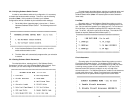
NOTE
1
: The 511 BER pattern can also be activated using the
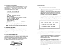
software control port. Follow these steps: From a terminal, first go
to the Main Menu and select item 3 to display the Software Switch
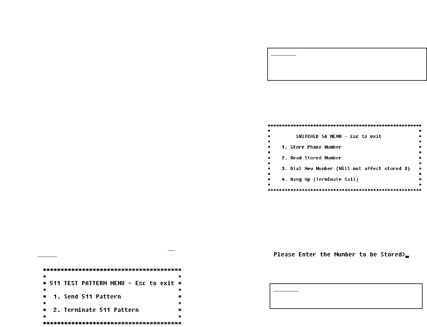
Menu (Section 3.2.4) In the Software Switch Menu, select item “c”
to go to the Send 511 Pattern Menu (see below). To send a 511
pattern, select item 1.
NOTE
2
: Control Port activation of the “511E” pattern is not
possible. The “511E” pattern may only be activated using the front
panel toggle switch.
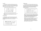
5.5 SWITCHED 56 DIALING COMMANDS (MODELS 2510RC &
2520RC)
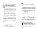
To access the Switched 56 dialing capabilities of the Mode 2500RC
Series, go to the Main Menu (see Section 3.2.4) and select item 5, “Set
Switched 56 Dialing Parameters”. This will take you to the Switched 56
Menu (see below). The following paragraphs describe the commands
in the Switched 56 Menu.
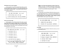
Store Phone Number (Enable DTR Dialing)
Selecting item 1 in the Dial Menu lets you activate the Model
2500RC Series’ “DTR Dialing” feature by storing a phone number in the
unit’s non-volatile memory. The Model 2500RC Series automatically
dials this number when the DTE raises the DTR lead. When you issue
this command, the Model 2500RC Series responds with this prompt:
Enter up to 12 digits (without hyphens or other alphabetic characters),
followed by [RETURN]. For example: “13015551212.”
NOTE: To disable DTR dialing, press [RETURN] (and nothing
else) when asked to enter the number to be stored.
CAUTION! Pressing [RETURN] by itself will erase any
previously stored number from the unit’s non-volatile memory
and cannot be undone. This will also disable DTR dialing.
CAUTION! For proper Switched 56 operation, you must enable
the Circuit Assurance and Force RTS options as described in
Section 4.0. Failure to do so may prevent the Model 2500RC
Series unit from answering incoming Switched 56 calls.