


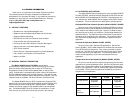
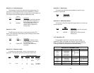
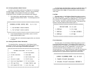
3.1.1 Switch Set “S1”
The configuration switches on switch set S1 allow you to specify
Line Rate, Circuit Assurance, RTS, Character Length, Data Format and
DSR Loop Status. The table below summarizes S1 switch settings,
including the factory defaults. Following the table are descriptions of
each switch setting.
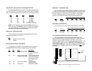
Switches S1-1. S1-2 and S1-3: Line Rate
These switches control the signalling rate on the line or RJ-48S
port of the unit. They should be set to match the speed of your digital
service.
S1-1
S1-2 S1-3 Setting
On On On 2.4 Kbps
On On Off 4.8 Kbps
On Off On 9.6 Kbps
On Off Off 19.2 Kbps
Off On On 56 Kbps
Off On Off 64 Kbps
Off Off Off Force configuration
pointer to default to
Hardware Switches
(See Section 3.2)
For line rates of 56 and 64 kbps, it is possible to operate the DTE
interface at a lower rate. To do this, set these switches to 56 or 64 kbps
and set the Rate Converter/DTE Rate switches as required.
3.0 CONFIGURATION
Before you can install and operate your Model 2500RC Series
CSU/DSU, you must configure both the front and rear cards. The
Model 2500RC Series has two sets of eight switches (S1 and S2), a
reversible interface driver board and two Rotary Address switches
(MSD and LSD). The 2500RC also has software switches which may
be configured with the Patton Model 1000CC control card (not
supplied), using a VT-100 type RS-232 terminal. Rear card
configuration is accomplished by means of hardware straps.
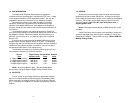
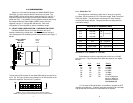
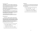
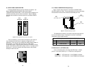
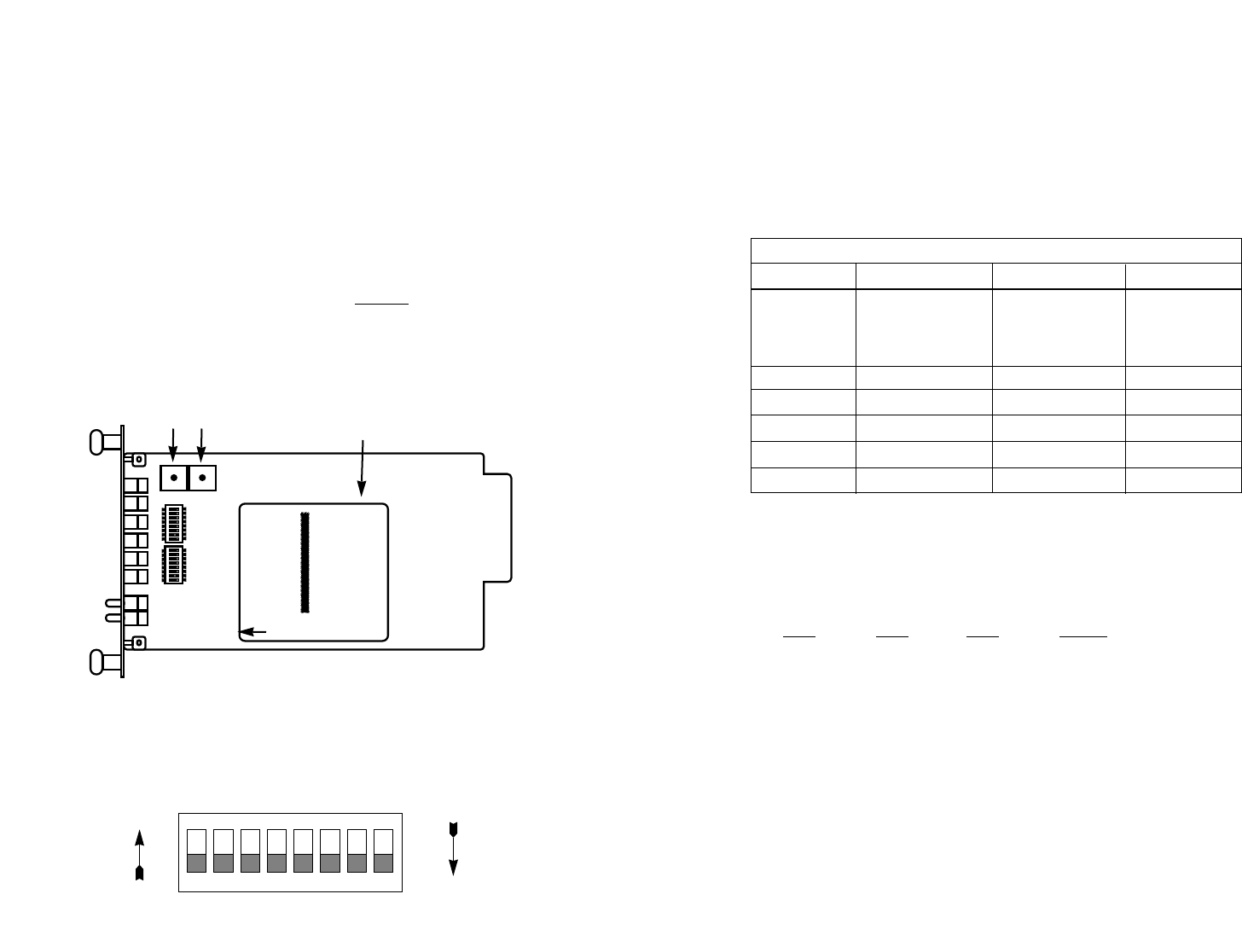
3.1 FRONT CARD CONFIGURATION - HARDWARE SWITCHES
The Model 2500RC Series front card defaults
to the use of
hardware switches for configuration. Hardware switches consist of
two eight-position DIP switches, and two rotary switches (see Figure 1,
below).
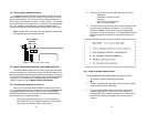
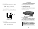
The two sets of DIP switches on the Model 2500 Series are referred to
as S1, S2. As Figure 2 shows, the orientation of all DIP switches is the
same with respect to “ON” and “OFF” positions.
87
SWITCH SET S1 SUMMARY TABLE
56,000 bps
}
Position Function Factory Default Exceptions
S1-1 Line Rate Off
S1-2 Line Rate On
S1-3 Line Rate On
S1-4 Circuit Assurance Off Disabled
Model 2510:Enabled
S1-5 RTS Off Forced On
S1-6 Character Length Off 10-Bit
S1-7 Data Format Off Synchronous
S1-8 DSR Loop Status Off DSR Off
Figure 1. Model 2500RC Series front card, showing location of switches
ON
12345678
ON
12345678
SW2
SW1
Interface
Driver
Board
FRONT
LSD
MSD
Rotary Address
Switches
12345678
ON
OFF
ON
Figure 2. Close up of DIP switches showing ON/OFF positions.
NOTE: The ON position is oriented toward the front of the Model 1092RC.
THIS SIDE UP FOR V.35