


33 34
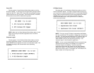
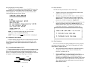
5.3.2 Remote Digital Loopback (RDL)
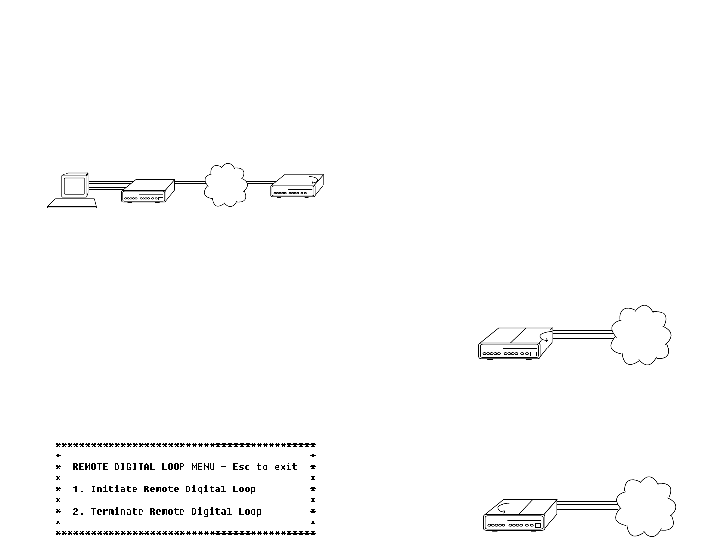
The Remote Digital Loopback (RDL) test checks the performance of
both the local and remote Model 2500RC Series',
and
the
communication link between them. Any characters sent to the remote
Model 2500RC Series in this test mode will be returned back to the
originating device. For example, characters typed on the keyboard of
the local terminal will appear on the local terminal screen
after
having
been passed to the remote Model 2500RC Series and looped back
(see Figure 12, below).
RDL Test Activation
The RDL test may be activated in one of three ways:
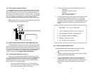
1) Toggle the front panel “Local/Normal/Remote” switch to the left
hand side to the “Remote” position.
2) Activate the RL lead from the DTE (Note: in order to use this
option, the DTE Loop Control option must be enabled–see
Section 3.2.4). If you are not sure which pin is the RL lead, please
refer to the pinout diagrams in Appendix D.
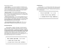
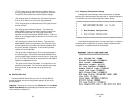
3) From a terminal, first go to the Main Menu and select item 3 to
display the Software Switch Menu (Section 3.2.4) In the
Software Switch Menu, select item “d” to go to the Set
Remote Digital Loop Menu (see below). To activate RDL, select
item 1.
RDL Test Procedure
Once LAL is activated, the “Test” LED should be lit. Perform a BER
(bit error rate) test on the system, using BER testers on both ends. If
the BER test equipment indicates a fault and the Local Analog
Loopback test was successful for both Model 2500RC Series units, you
may have a problem with the line between the CSU/DSUs. You should
inspect the line for proper connections.
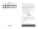
5.3.3 Telco Testing
The digital service provider’s central office can perform CSU Loop
and DSU Loop diagnostic testing. These diagnostics allow the central
office to evaluate circuit operation without making visits to a customer’s
premises.
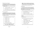
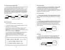
CSU Loop
The CSU Loop is activated when the central office reverses the DC
sealing current that flows between the TX pair and the RX pair. In this
case, the Model 2500RC Series recognizes this and loops signals on
the RX pair back to the central office on the TX pair (see Figure 13,
below). While the CSU Loop is activated by the central office, the TM
light is illuminated.
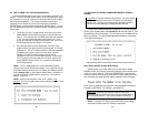
DSU Loop
The DSU Loop is activated when the central office sends a DSU
loop signal over the twisted pair wire. The Model 2500RC Series
senses this signal and loops the digital data back to the central office
(see Figure 14, below). While the DSU Loop is activated, the TM light
is illuminated.
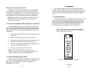
CSUDSU Digital Network
Figure 13. CSU loop
CSUDSU
Digital Network
Figure 14. DSU loop
Digital Network
CSU/DSU
Figure 12. Remote digital loop