45
5.0 OPERATION
Once the Model 3088RC is properly conÞgured and installed, it should
operate transparently. These sections describes functions of the LED
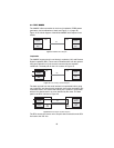
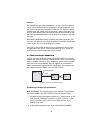
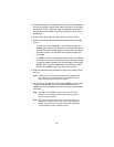
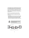
status indicators, and the use of the built-in loopback test modes.
5.1 LED STATUS INDICATORS
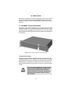
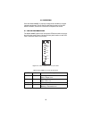
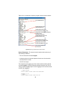
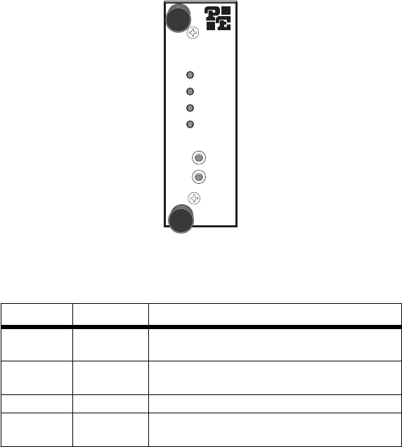
The Model 3088RC features four front panel LEDs that monitor the opera-
tion of the rack card. Figure 17 shows the front panel location of each LED.
Table 1 describes each LED’s function.
Figure 17. The Model 3088RC Series’ front panel LEDs
Table 1: Model 3088RC front panel LED descriptiont
LED Color Description
Power Green Flashing = POST
Solid = Power is on
DSL Green Flashing = Training
Solid = DSL Link
TERM Yellow Solid = Serial port is active
TM/ER Green Solid = Test mode is active
Blinking = Test mode error
3088RC
RocketLink-G NTU
–Power
–DSL
–TERM
–TM/ER
Remote Local
511 511/E


