


53
APPENDIX A
SPECIFICATIONS
A.1 CLOCKING MODES
Internal, external (V.35 only), or receive recovered
A.2 DTE RATE
All 64k steps from 64 to 4608 kbps
A.3 SERIAL INTERFACE
V.35 (Model 3088RC/A/I), DCE orientation;
X.21 (Model 3088RC/D/V), DCE or DTE orientation depending on orien-
tation of daughter board mounted on the mother board.
E1 (Model 3088RC/K/K) presents G.703/G.704 interface. Either 75
Ohms (unbalanced) or 120 Ohms (balanced). Pins 1 & 2 are Receive.
Pins 4 & 5 are Transmit.
A.4 SERIAL CONNECTOR
D-Sub-25 Female (Model 3088RC/A/I)
D-Sub-15 Female (Model 3088RC/D/V)
Dual BNC and RJ48C (Model 3088RC/K/K), strap selectable
A.5 DIAGNOSTICS
V.52 compliant (511/511E) pattern generator and detector with error
injection mode controlled by front-panel switch. Local and Remote Loop-
back control either by a front-panel switch or from the DTE interface.
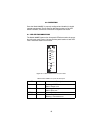
A.6 STATUS LEDS
• Power (Green): The Power LED glows solid during normal operation.
At startup, during the POST, the LED blinks once every second.
• DSL (Green): The DSL LED glows solid when a DSL link is estab-
lished. While the DSL link is training, it blinks once every second.
• Term (Yellow): The Term LED glows solid when a serial port is active.
• TM/ER (Green): The Test Mode/Error (TM/ER) LED is used to indicate
that a test mode is in progress or an error has been detected. It blinks
once every second while a test mode is starting. It glows solid while a