


C2624M (6/07) 11
REAR PANEL
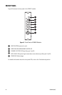
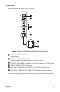
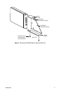
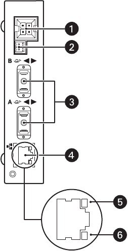
Figure 4 illustrates the rear panel of the FX82012 module.
Figure 4. Rear Panel of FX82012 Module (SC Fiber Connectors Shown)
For additional information about rear-panel connections, refer to the Installation section. For detailed
information about the RJ-45 LEDs, refer to the Troubleshooting section.
ì RACK POWER/ALARM CONNECTOR, 4-pin connector for power/alarm connection of rack-
mounted module
î STAND-ALONE POWER CONNECTOR, 2-pin connector for power connection of stand-alone
module; removable mating connector with screw terminals (not shown)
ï
FIBER OPTIC PORTS A AND B, single-fiber ST or SC connectors (dependent on FX82012 model)
ñ
10BASE-T/100BASE-TX PORT, RJ-45 connector
ó
RJ-45 10BASE-T/100BASE-TX PORT STATUS LED, LEFT (link/activity status indicator)
r
RJ-45 10BASE-T/100BASE-TX PORT STATUS LED, RIGHT (duplex mode/collision indicator)