


C2624M (6/07) 15
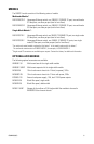
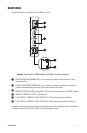
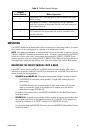
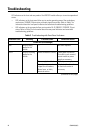
Table B. FX Mode Switch Settings
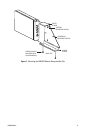
MOUNTING
The FX82012 module can be mounted into a rack or can be used as a stand-alone module. As a stand-
alone module, the unit can be placed on a desktop or can be mounted to a wall.
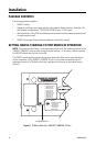
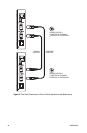
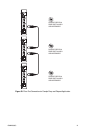
NOTE: As a matter of convenience, it is recommended that you set the modes of operation for each
10BASE-T/100BASE-TX port and the fiber failover mode—if required—before mounting the FX82012
module into a rack or onto a wall. For information about setting the 10BASE-T/100BASE-TX port
modes of operation, refer to the Setting 10BASE-T/100BASE-TX Port Modes of Operation section. For
information about setting the fiber failover mode, refer to the Setting Fiber Failover Mode section.
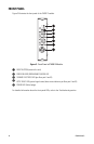
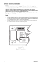
MOUNTING THE FX82012 MODULE INTO A RACK
The FX82012 module can be installed into an RK5000 Series rack mount chassis, which can be
mounted into an industry-standard 19-inch (48.26 cm) equipment rack. The RK5000 Series rack mount
chassis includes the following models:
• RK5000PS-3U and RK5000-3U: Designed to accommodate fiber optic modules as follows:
– The RK5000PS-3U rack mount chassis provides 12 single-width module slots and a
power supply.
– The RK5000-3U rack mount chassis provides 14 single-width module slots (a power
supply is not included). Power to the modules can be supplied using the optional
external power supply (EPS5000-120).
For additional information, refer to the RK5000PS-3U/RK5000-3U Fiber Rack Mount Chassis
Installation manual.
• RK5000PS-5U: Designed to accommodate Endura
™
modules but can also accommodate fiber
optic modules with the use of the appropriate adapter kit. The RK5001-1UEXP adapter kit is
required for installation of the FX82012 module into the RK5000PS-5U chassis.
For information about the RK5000PS-5U chassis, refer to the RK5000PS-5U Rack Mount Chassis
Installation manual.
FX Mode
Switch Position Mode of Operation
0
Independent A & B—Sets fiber ports A and B in nonredundant mode
(default setting).
1
Auto Failover, A is Primary—Sets fiber ports A and B in redundant
mode. Port A connects to the primary fiber link, and Port B connects to
the secondary fiber link.
2
Auto Failover, B is Primary—Sets fiber ports A and B in redundant mode.
Port B connects to the primary fiber link, and Port A connects to the
secondary fiber link.
3-9 Not used