


C2624M (6/07) 19
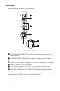
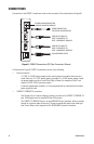
• Fiber connections
– When connecting fiber between FX82012 models, connect fiber port A of one module to
fiber port B of another module. Similarly, connect fiber port B of one module to fiber
port A of another module. Note that ports A and B connect fiber between FX82012
models because of fiber wavelength compatibility:
• Multimode fiber port A transmits data at 1310 nm and receives data at 850 nm.
Multimode fiber port B transmits data at 850 nm and receives data at 1310 nm.
• Single-mode fiber port A transmits data at 1310 nm and receives data at 1550 nm.
Single-mode fiber port B transmits data at 1550 nm and receives data at 1310 nm.
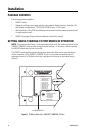
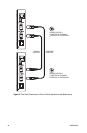
Refer to Figure 9 for an illustration of fiber port connections in a point-to-point application
with redundancy. Note that the FX Mode switch is set on one module to position 1 (fiber
port A connects to the primary fiber link) and is set on the other module to position 2 (fiber
port B connects to the primary fiber link).
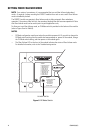
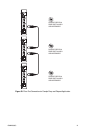
Refer to Figure 10 for an illustration of fiber port connections in drop-and-repeat
applications. Note that the FX Mode switch is set to position 0 on all modules.