


18 C2624M (6/07)
CONNECTIONS
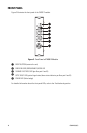
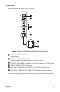
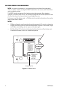
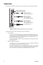
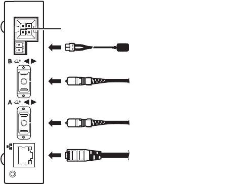
Connections to the FX82012 module are made on the rear panel of the module (refer to Figure 8).
Figure 8. FX82012 Connections (SC Fiber Connectors Shown)
As illustrated in Figure 8, FX82012 connections consist of the following:
• Power connection
– A 12 VDC or 24 VAC power supply can be used to power the module when used as a
stand-alone unit. A 12 VDC power supply is provided. If a 24 VAC power supply is used,
the power supply must be a Listed Direct Plug-In Power Unit marked as Class 2 and
rated as 24 VAC, 0.50 A (minimum output).
– In extreme temperature conditions, it is recommended that an industrial-rated outdoor
power supply be used.
• 10BASE-T/100BASE-TX connection
– Use Category 5e or a higher category of cable to connect to the 10BASE-T/100BASE-TX
port. Cable length must not exceed 328 feet (100 meters).
– The 10BASE-T/100BASE-TX port is an auto MDI/MDI-X port; therefore, either a straight-
through or crossover cable can be used. The port automatically detects the cable type
that is used. Refer to the Appendix for RJ-45 MDI/MDI-X pinout information.
10/100 NETWORK CABLE
FIBER OPTIC CABLE TO
PORT B (CONNECTS TO
PORT A ON REMOTE MODULE)
POWER CONNECTION
FOR STAND-ALONE MODULE
POWER/ALARM CONNECTION
FOR RACK-MOUNTED MODULE
FIBER OPTIC CABLE TO
PORT B (CONNECTS TO
PORT A ON REMOTE MODULE)