


Application for PM2812 and PM2813 D - 1
APPENDIX D
APPLICATION FOR PM2812 AND PM2813
The followin
g
application support information is meant for the user who wants to
extend the maximum current of the PM2812 or PM2813 Power Supply by parallel
connection of channels.
PARALLEL CONNECTION OF OUTPUT CHANNELS
When you connect output channels in parallel to a load, be aware of the followin
g
:
The 'down pro
g
rammer'
This is a circuit in the output channel that unloads the internal filter capacitors
when the output volta
g
e is set to a lower value, to achieve a short response time.
The down pro
g
rammer will have the same effect on (external) capacitive loads to
shorten the response time. The down pro
g
rammer will sink a fixed current (about
10% of the rated current) as lon
g
as the volta
g
e on the channel output is hi
g
her
than the pro
g
rammed settin
g
.
The down pro
g
rammer will influence also the result of parallel connected
channels when the channels are set to different volta
g
es. The channel set to the
lowest volta
g
e will activate its down pro
g
rammer, which will behave as a constant
current load. This current is not shown by the display or by readback. Then the
total current throu
g
h the load is not equal to the total readback current of the
channels.
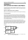
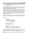
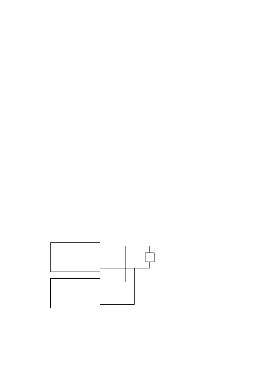
Example:
Fi
g
ure D.1 Channels connected in parallel to a load. CH 1 in Constant Current
mode, CH 2 in Constant Volta
g
e mode.
Vset = 12V
Iset = 5A
1.25Ω
10V
8A
CC
5A
10V
CH1
Vset = 10V
Iset = 5A
CV
3A
10V
CH2