


3 - 8 Users Manual
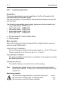
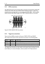
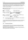
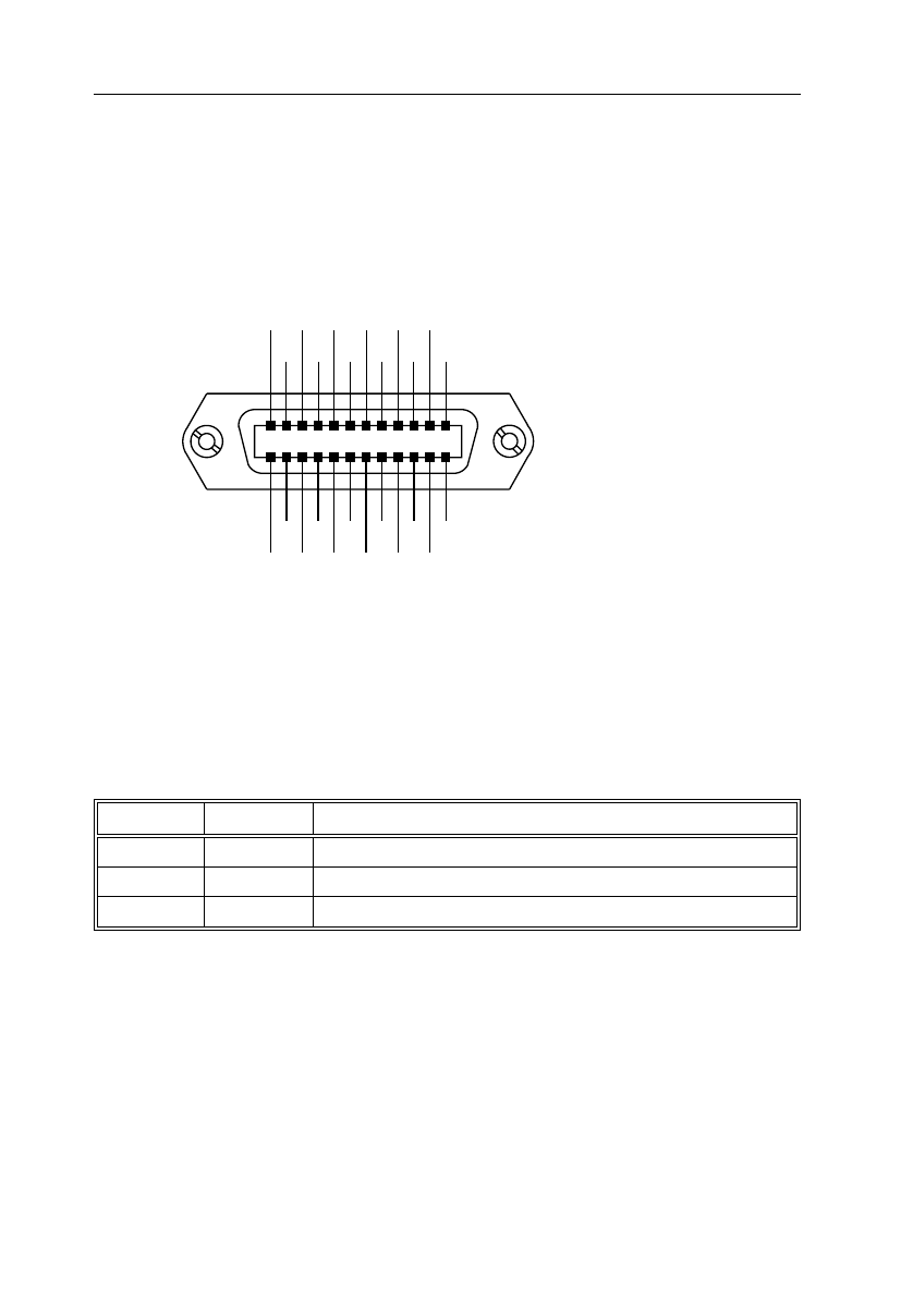
3.5.2 GPIB connections
The GPIB (General Purpose Interface Bus) is identical to the IEC 625 or IEEE 488
interface bus. At the rear you will find a 24-pin female connector in which the
connector pinnin
g
assi
g
nment is in accordance with IEEE 488.2 - 1987. An IEEE
cable connects your power supply via an IEEE interface board to a controller.
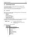
3.5.3 Tri
gg
er bus connections
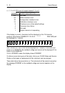
There are three SMB connectors at the rear: START, STEP, and READY.
The modes and functions of the connectors are shown in the followin
g
table.
The tri
gg
er bus connectors can be used to recall output channel settin
g
s from the
recall memory. For more information, refer to section 5.5.5 "Step functions".
Fi
g
ure 3.4 IEEE 488/IEC 625 Connections
SHIELD
ATN
SRQ
IFC
NDAC
NR
FD
DAV
DIO4
DIO2
EO1
DIO3
DIO1
GND
11
GND
9
GND
7
REN
DIO7
DIO5
LOGIC
GND
GND
10
GND
8
GND
6
DIO8
DIO6
ST6064
12
24
1
13
NAME MODE FUNCTION
START input Enables steppin
g
via the STEP input.
STEP input Executes the next step.
READY output Indicates whether a step is finished (ready for the next step).