


5 - 16 Users Manual
• I
set
= 0.5A Maximum current throu
g
h the load becomes 0.5A.
• OVP
set
= 7V Overvolta
g
e protection trip level becomes 7V.
Sequentially the volta
g
es 2V, 4V, 6V, and 8V will be pro
g
rammed:
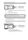
• V
set
= 2V I
load
= V
set
/ R
load
=2V/10Ω = 0.2A.
The output channel stays in the CV mode.
• V
set
= 4V I
load
= V
set
/ R
load
= 4V/10Ω = 0.4A.
The output channel stays in the CV mode.
•V
set
= 6V I
load
= V
set
/ R
load
= 6V/10Ω = 0.6A. However, the maximum
output current (0.5A) is
g
oin
g
to be exceeded. Therefore, the
current throu
g
h the load becomes 0.5A and the volta
g
e
across the load is limited at 0.5A x 10Ω = 5V.
The output channel
g
oes into the CC mode.
• I
set
= 1A The maximum current throu
g
h the load becomes 1A.
I
load
= V
set
/ R
load
= 6V/10Ω = 0.6A. The volta
g
e across the
load becomes 0.6A x 10Ω = 6V.
The output channel
g
oes back into the CV mode.
•V
set
= 8V Now the overvolta
g
e protection trip level OVP
set
(7V) is
g
oin
g
to be exceeded. This will activate the overvolta
g
e protection
circuitry, so the output volta
g
e and current will be reduced to
zero. Also the messa
g
e OVERVOLTAGE will be displayed.
• OVP
set
= 9V The overvolta
g
e protection trip level becomes 9V.
• RESET The overvolta
g
e protection circuitry is reset, and the volta
g
e
across the load becomes 8V.
I
load
= V
set
/ R
load
= 8V/10Ω = 0.8A.
The output channel remains in the CV mode.