


Philips Semiconductors Product specification
PTN3501Maintenance and control device
2
2001 Jan 17 853-2227 25436
FEATURES
• I
2
C to parallel port expander
• Internal 256x8 E
2
PROM
• Self timed write cycle (5 ms typ.)
• 16 byte page write operation
• Controlled pull-up on address lines
• Low voltage V
CC
range of +2.5 V to +3.6 V
• 5 V – tolerant I/Os
• Low standby current (< 60 µA )
• Power on Reset
• Supports Live Insertion
• Compatible with SMBus specification version 1.1
• High E
2
PROM endurance and data retention
• Available in TSSOP20 package
DESCRIPTION
The PTN3501 is a general purpose maintenance and control device.
It features an on-board E
2
PROM that can be used to store error
codes or board manufacturing data for read–back by application
software for diagnostic purposes.
The eight quasi bidirectional data pins can be independently
assigned as inputs or outputs to monitor board level status or
activate indicator devices such as LEDs.
The PTN3501 has six address pins allowing up to 64 devices to
share the common two wire I
2
C software protocol serial data bus.
The PTN3501 supports live insertion to facilitate usage in removable
cards on backplane systems.
The PTN3501 is an alternative to the functionally similar PTN3500
for systems where a high number of devices are required to share
the same I
2
C-bus without need for an additional I
2
C-bus I/O
expander.
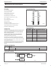
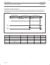
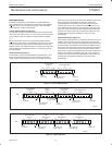
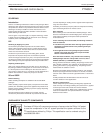
PIN CONFIGURATION
1
2
3
4
5
6
7
20
19
18
17
16
15
14
A0
A1
A2
P0
P1
P2
P3
SDA
SCL
P7
P6
P5
WC
V
DD
SW00657
PTN3501
8
13
P4
9
10
12
11
A5 A3
A4
V
SS
INT
Figure 1.
PIN DESCRIPTION
PIN NUMBER SYMBOL NAME AND FUNCTION
1,2,3,9,11,12 A0:5 Address Lines
4,5,6,7 P0:3 Quasi–bidirectional I/O pins
10 V
SS
Ground
13,14,15,16 P4:7 Quasi–bidirectional I/O pins
17 WC Write Control Pin. Should be
tied LOW.
8 INT Interrupt Pin
18 SCL I
2
C Serial Clock
19 SDA I
2
C Serial Data
20 V
DD
Supply Voltage
ORDERING INFORMATION
Type n mber
Package
Type
n
u
mber
Name Description Version
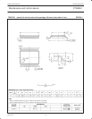
PTN3501DH TSSOP20 Plastic thin shrink small-outline package; 20 leads; body width 4.4 mm SOT360-1
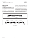
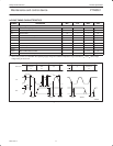
FUNCTIONAL DIAGRAM
I
2
C
CONTROL
8-BIT
I/O PORT
P7:0
A5:0
SDA
SCL
E2PROM
256 × 8
WC
INT
SW00647
Figure 2.