


Philips Semiconductors Product specification
PTN3501Maintenance and control device
2001 Jan 17
4
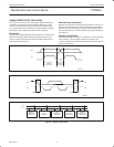
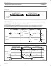
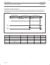
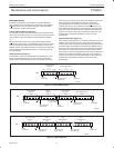
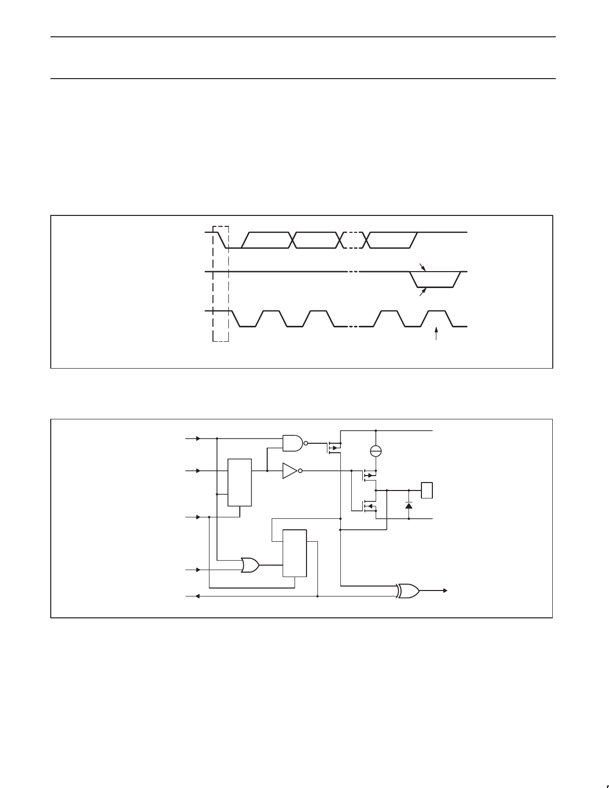
Acknowledge (see Figure 6)
The number of data bytes transferred between the start and the stop
conditions from transmitter to receiver is not limited. Each byte of
eight bits is followed by one acknowledge bit. The acknowledge bit
is a HIGH level put on the bus by the transmitter whereas the
master generates an extra acknowledge related clock pulse.
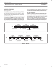
A slave receiver which is addressed must generate an acknowledge
after the reception of each byte. Also a master must generate an
acknowledge after the reception of each byte that has been clocked
out of the slave transmitter. The device that acknowledges has to
pull down the SDA line during the acknowledge clock pulse, so that
the SDA line is stable LOW during the HIGH period of the
acknowledge related clock pulse, set–up and hold times must be
taken into account.
A master receiver must signal an end of data to the transmitter by
not generating an acknowledge on the last byte that has been
clocked out of the slave. In this event the transmitter must leave the
data line HIGH to enable the master to generate a stop condition.
S
9821
SW00545
DATA OUTPUT
BY TRANSMITTER
DATA OUTPUT
BY RECEIVER
SCL FROM
MASTER
ACKNOWLEDGE
NOT ACKNOWLEDGE
CLOCK PULSE FOR
ACKNOWLEDGEMENT
START
CONDITION
Figure 6. Acknowledgment on the I
2
C-bus
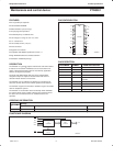
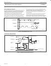
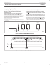
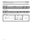
FUNCTIONAL DESCRIPTION
SW00788
WRITE PULSE
DATA FROM
SHIFT REGISTER
POWER-ON
RESET
READ PULSE
DATA TO
SHIFT REGISTER
V
DD
P0 TO P7
V
SS
100 µA
C
I
S
DQ
FF
C
I
S
DQ
FF
TO INTERRUPT LOGIC
Figure 7. Simplified schematic diagram of each I/O