


Philips Semiconductors Product specification
PTN3501Maintenance and control device
2001 Jan 17
5
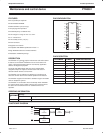
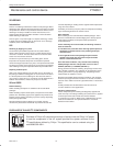
Addressing
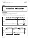
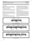
For addressing, see Figure 8.
S 0 A5 A4 A3 A2 A1 A0 0 A A5 0 AS 1 A4 A3 A2 A1 A0
a. b.
(a) I/O EXPANDER
(b) MEMORY
SW00648
SLAVE ADDRESSSLAVE ADDRESS
Figure 8. PTN3501 slave addresses
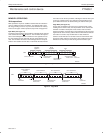
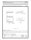
Asynchronous Start
Following any Start condition on the bus, a minimum of 9 SCL clock cycles must be completed before a Stop condition can be issued. The
device does not support a Stop or a repeated Start condition during this time period.
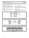
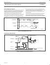
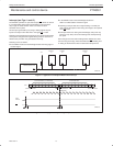
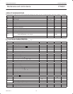
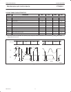
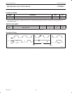
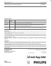
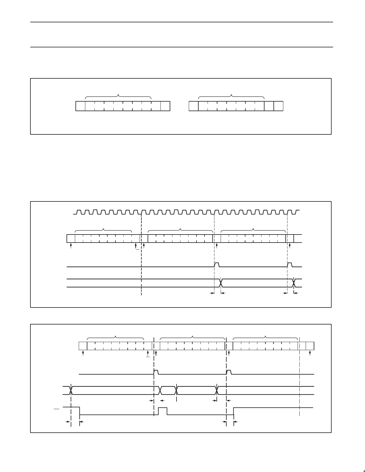
I/O OPERATIONS (see also Figure 7)
Each of the PTN3501’s eight I/Os can be independently used as an input or output. Input I/O data is transferred from the port to the
microcontroller by the READ mode (See Figure 10). Output data is transmitted to the port by the I/O WRITE mode (see Figure 9).
S 0 A5 A4 A3 A2 A1 A0 0 A DATA 1 A DATA 2 ASDA
SCL
t
pv
12345678
t
pv
DATA 2 VALIDDATA 1 VALID
SW00649
ACKNOWLEDGE
FROM SLAVE
R/WSTART CONDITION ACKNOWLEDGE
FROM SLAVE
ACKNOWLEDGE
FROM SLAVE
SLAVE ADDRESS (I/O EXPANDER)
DATA TO PORT
DATA TO PORT
WRITE TO
PORT
DATA OUT
FROM PORT
Figure 9. I/O WRITE mode (output)
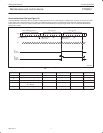
S 0 A5 A4 A3 A2 A1 A0 1 A DATA 1 A
DATA 4
1SDA
t
ph
t
ps
DATA 4
P
DATA 2 DATA 3
SW00650
SLAVE ADDRESS (I/O EXPANDER) DATA FROM PORT DATA FROM PORT
READ FROM
PORT
DATA INTO
PORT
START CONDITION ACKNOWLEDGE
FROM SLAVE
R/W ACKNOWLEDGE
FROM MASTER
STOP
CONDITION
DATA 1
INT
t
iv
t
ir
Figure 10. I/O READ mode (input)